


Reducing Flange Performance Analysis
Introduction
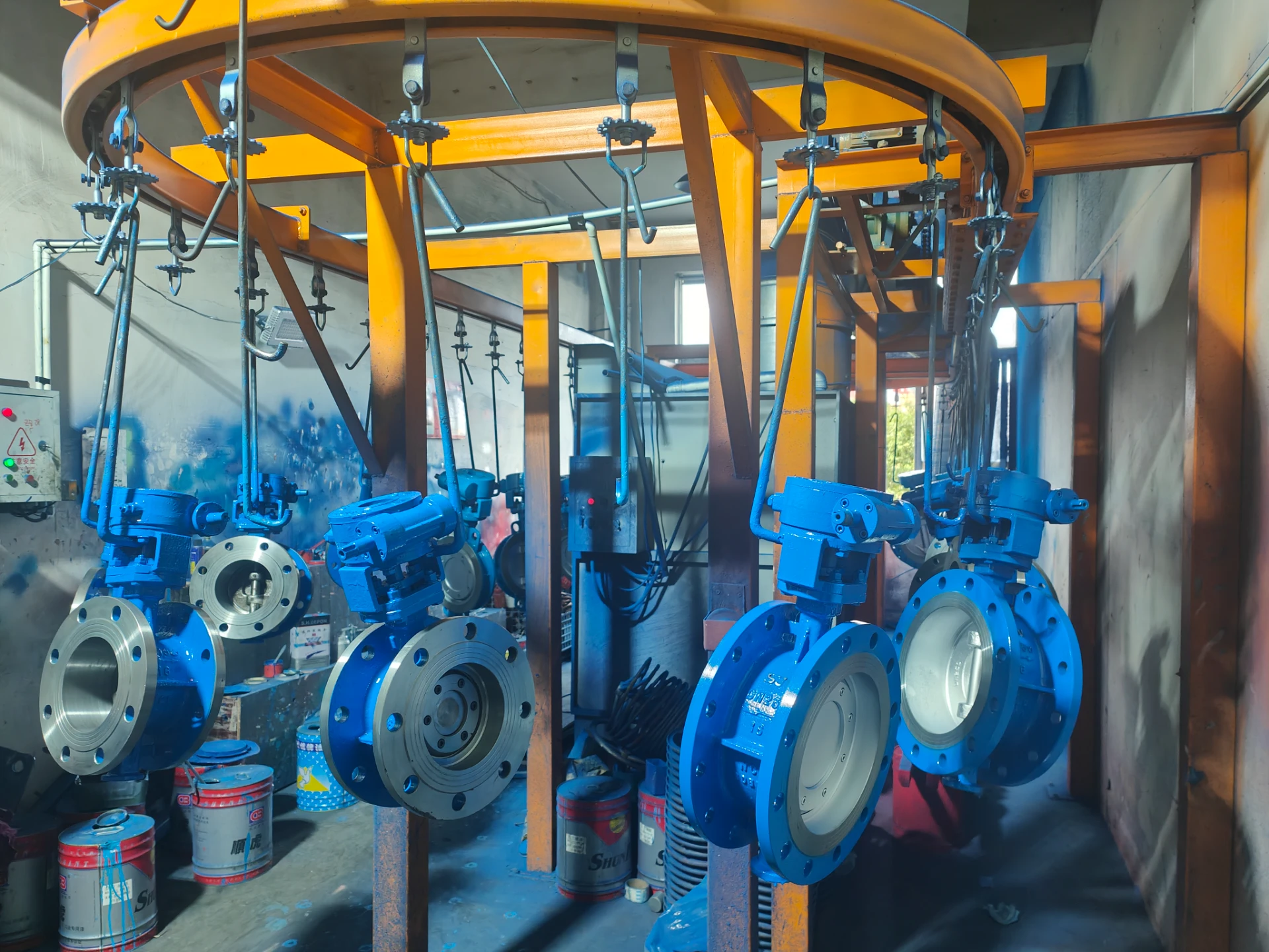
A reducing flange is a pipe fitting used to connect sections of pipe with different diameters. Positioned within the piping system, it facilitates the transition between two differing pipe sizes, offering a crucial component for process flow adjustments and system integration. Its primary function is to reduce flow restriction while maintaining structural integrity. Unlike weld-neck or slip-on flanges, a reducing flange incorporates a tapered hub, allowing direct connection to a smaller diameter pipe. This eliminates the need for additional reducers, streamlining the piping configuration and potentially reducing overall costs and weld points. Applications span a vast range of industries, including petrochemical, power generation, water treatment, and shipbuilding. Understanding the material science, manufacturing processes, performance characteristics, and potential failure modes of reducing flanges is critical for ensuring long-term operational reliability and safety.
Material Science & Manufacturing
Reducing flanges are commonly manufactured from carbon steel (ASTM A105, A36), stainless steel (304/304L, 316/316L), alloy steel (A182 F22, F91), and occasionally ductile iron. The selection of material is dictated by the operating temperature, pressure, fluid composition, and corrosion potential of the application. Carbon steel provides good strength and cost-effectiveness for general applications. Stainless steel offers superior corrosion resistance, crucial in environments with aggressive chemicals or saltwater exposure. Alloy steels are employed in high-temperature, high-pressure services.
The manufacturing process typically begins with forging or casting of the flange body. Forging offers enhanced mechanical properties due to grain flow alignment, making it preferred for critical applications. Casting is more cost-effective for large production runs but may require additional heat treatment to achieve desired material characteristics. Following forging or casting, the flange undergoes machining to create precise dimensions, including the bore diameter, bolt hole patterns, and face finish. Key parameter control during machining includes maintaining concentricity between the bore and bolt circle to ensure proper gasket sealing. The tapered hub is machined to exacting tolerances to ensure a smooth transition to the smaller diameter pipe. Finally, flanges are often subjected to non-destructive testing (NDT) such as dye penetrant inspection, radiography, or ultrasonic testing to verify the absence of internal flaws. Welding procedures (SMAW, GTAW, GMAW) used to connect the flange to the piping system must adhere to relevant codes (ASME Section IX) and qualified welder performance qualifications.

Performance & Engineering
The performance of a reducing flange is fundamentally governed by its ability to withstand internal pressure and external loads without failure. Stress analysis, employing Finite Element Analysis (FEA) techniques, is crucial during the design phase to predict stress concentrations around the tapered hub and bolt holes. The flange facing (Raised Face, Flat Face, Ring Type Joint) impacts the sealing performance and the choice of gasket material. Raised Face flanges typically use spiral wound gaskets, offering high sealing efficiency. Flat Face flanges are used with full-face gaskets for applications requiring a leak-tight seal on uneven surfaces. Ring Type Joint (RTJ) flanges are employed in high-pressure, high-temperature services where metallic seals are required.
Environmental resistance is a critical consideration. Corrosion, erosion, and fatigue can all compromise the integrity of the flange. Material selection plays a key role in mitigating corrosion. Protective coatings, such as epoxy or galvanizing, can further enhance corrosion resistance. Erosion, caused by the flow of abrasive particles, can be addressed through the use of hardened materials or erosion-resistant coatings. Fatigue, resulting from cyclic loading, is particularly relevant in applications subject to vibration or pressure fluctuations. Proper design, including optimized stress distribution and surface finish, can minimize fatigue crack initiation and propagation. Compliance requirements depend on the specific application and industry. For pressure vessels, ASME Section VIII Division 1 dictates design and fabrication standards. For pipelines, API 5L and ASME B31.3 provide guidance on material selection, welding, and inspection. Leak testing is essential to verify the integrity of the connection after installation.
Technical Specifications
| Parameter | Unit | ASTM A105 Carbon Steel | 304/304L Stainless Steel |
|---|---|---|---|
| Pressure Rating | psi | Up to 2000 | Up to 3000 |
| Temperature Range | °F | -20 to 650 | -325 to 850 |
| Tensile Strength | MPa | 580 - 760 | 517 - 724 |
| Yield Strength | MPa | 310 - 483 | 205 - 550 |
| Elongation | % | 18-23 | 30-45 |
| Hardness (Brinell) | HB | 140-210 | 95-115 |
Failure Mode & Maintenance
Reducing flanges are susceptible to several failure modes. Corrosion is a primary concern, particularly in aggressive environments. Pitting corrosion, crevice corrosion, and galvanic corrosion can all lead to material degradation and eventual failure. Erosion, caused by the impact of solid particles in the fluid stream, can wear away the flange material, especially at the inner diameter of the tapered hub. Fatigue cracking can occur under cyclic loading, initiating at stress concentrations around bolt holes or weld toes. Leakage can result from gasket failure, caused by improper installation, material incompatibility, or exceeding the gasket’s pressure-temperature rating. Bolted joint failure, stemming from insufficient bolt preload or corrosion of the bolts, is another common issue.
Preventative maintenance is crucial for extending the service life of reducing flanges. Regular visual inspections should be conducted to identify signs of corrosion, erosion, or cracking. Torque checks on the flange bolts should be performed periodically to ensure proper preload. Gaskets should be replaced as part of a scheduled maintenance program. Non-destructive testing (NDT) methods, such as ultrasonic testing or radiography, can be used to detect internal flaws before they lead to catastrophic failure. For flanges operating in corrosive environments, protective coatings should be reapplied as needed. In cases of localized corrosion, localized repairs using welding or composite materials may be feasible. Complete flange replacement should be considered if the extent of damage is significant.
Industry FAQ
Q: What is the impact of differing thermal expansion rates between the flange material and the connected piping?
A: Differing thermal expansion rates can induce significant stress on the flange and bolted connection. When the piping and flange expand or contract at different rates due to temperature changes, it creates bending moments and shear forces. This can lead to bolt loosening, gasket failure, and ultimately, leakage. Mitigation strategies include selecting materials with similar thermal expansion coefficients, using expansion joints to accommodate thermal movement, and carefully controlling the tightening sequence of the flange bolts.
Q: How does the surface roughness of the flange facing affect the gasket performance?
A: Surface roughness directly impacts the gasket's ability to achieve a leak-tight seal. Excessive roughness creates voids between the flange faces and the gasket, providing pathways for fluid leakage. The specified surface roughness (typically measured in Ra – arithmetic average roughness) depends on the flange facing type and gasket material. Generally, finer surface finishes are required for applications demanding high sealing integrity.
Q: What are the key considerations when selecting a gasket material for a reducing flange application?
A: Gasket material selection involves several key considerations. Fluid compatibility is paramount – the gasket must resist chemical attack from the process fluid. Temperature and pressure ratings must be appropriate for the operating conditions. The gasket material must also exhibit sufficient resilience and recovery to maintain a seal under varying loads. Common gasket materials include spiral wound, sheet rubber, and PTFE.
Q: How do you determine the appropriate bolt preload for a reducing flange connection?
A: Determining the correct bolt preload is crucial for ensuring a proper seal and preventing joint failure. Under-tightening can lead to leakage, while over-tightening can damage the flange or bolts. Bolt preload is typically calculated based on the flange size, pressure rating, and bolt material. Torque wrenches and calibrated bolt tensioners are used to achieve the desired preload. Following established bolting procedures (ASME PCC-1) is essential.
Q: What is the significance of hydrotesting a piping system containing reducing flanges?
A: Hydrotesting (or pneumatically testing with extreme caution) is a critical step in verifying the integrity of the piping system after installation. It involves pressurizing the system with a test fluid (typically water) to a pressure exceeding the maximum operating pressure. This tests the strength and leak-tightness of all components, including the reducing flanges and their connections. Any leaks or structural failures identified during hydrotesting must be addressed before the system is put into service.
Conclusion
The reducing flange, while seemingly a simple component, plays a vital role in piping systems across numerous industries. Its effective performance relies heavily on a thorough understanding of material properties, manufacturing precision, and engineering principles. Proper material selection, aligned with the application’s specific operating conditions and fluid compatibility, is fundamental. Precise machining and adherence to stringent quality control measures during manufacturing are critical to ensuring dimensional accuracy and structural integrity.
Moving forward, continued advancements in non-destructive testing methodologies and predictive maintenance techniques will enhance the reliability and longevity of reducing flange installations. Furthermore, the development of advanced materials with improved corrosion resistance and fatigue strength will broaden the application scope of reducing flanges in increasingly demanding environments. Adhering to established industry standards and best practices remains paramount for ensuring safe and efficient operation.
-
megalug flange Performance and Engineering
-
Plate Flange Performance Analysis
-
Reducing Flange Performance Analysis
-
Sealing Flange Performance Analysis
-
Turbo Flanges Performance Analysis
-
Screwed Flange Performance Analysis
-
Screwed Flanges Performance Analysis
-
Screw Flanges Performance Analysis
-
weld neck flanges Performance Analysis
-
welding neck flange Material Science Manufacturing
-
Raised Face Flange Performance Analysis
-
Threaded Flanges Performance Analysis
-
uni flange Performance Analysis
-
Thread Flange Material Science and Performance
-
Flange Welding Performance Analysis