


angle pattern globe valve Performance Analysis
Introduction
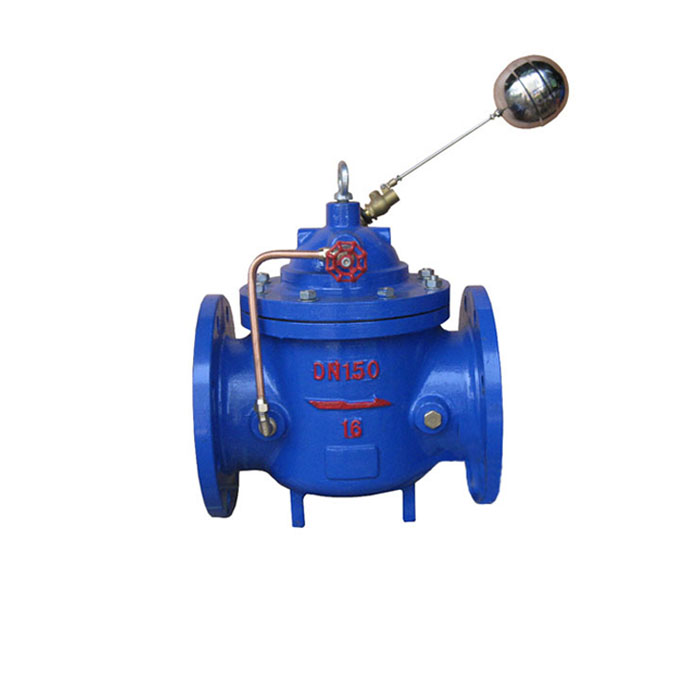
The angle pattern globe valve is a crucial flow control device utilized extensively in industrial processing, power generation, and fluid handling systems. Distinguished by its 90-degree angled body, this valve configuration offers a streamlined installation profile, particularly beneficial in constrained spaces and reducing pipeline stress. Unlike parallel seat gate valves, globe valves are designed for throttling and regulating flow, rather than simply on/off service. Their inherent design provides tighter shut-off capabilities, making them suitable for applications requiring minimal leakage. Within the industry chain, the angle pattern globe valve occupies a critical position between source fluid supply, processing equipment, and discharge points, necessitating high reliability and precise control. Core performance characteristics include Cv (flow coefficient), pressure drop, seat leakage class, and operational torque requirements, all dictating suitability for specific process conditions.
Material Science & Manufacturing
The body of an angle pattern globe valve is typically constructed from materials selected for their corrosion resistance, pressure-bearing capacity, and temperature tolerance. Common materials include ASTM A351 Grade CF8 (304 Stainless Steel), ASTM A351 Grade CF8M (316 Stainless Steel), and cast iron (ASTM A126 Class B). Stainless steels are favored in corrosive environments, offering excellent resistance to chloride pitting and crevice corrosion. Cast iron provides a cost-effective solution for less demanding applications. The disc, which directly controls flow, often utilizes alloys like Alloy 410 or 17-4PH stainless steel for enhanced wear resistance and hardness. Seat materials range from reinforced PTFE (Polytetrafluoroethylene) to metal-to-metal designs (e.g., hardened stainless steel) depending on temperature and pressure requirements. The manufacturing process typically begins with investment casting or sand casting for the body, followed by precision machining to achieve tight tolerances on internal diameters and seating surfaces. The disc is produced via forging or machining, then heat-treated for optimal strength and hardness. Key parameter control during manufacturing focuses on dimensional accuracy of the seat angles (typically 60 degrees), surface finish of the seating surfaces (Ra < 0.4 µm for tight shut-off), and hydrostatic shell testing to verify structural integrity under pressure. Welding processes, such as Gas Tungsten Arc Welding (GTAW) or Shielded Metal Arc Welding (SMAW), are employed for joining components, requiring strict adherence to ASME Section IX for weld qualification and inspection.
Performance & Engineering
The performance of an angle pattern globe valve is governed by principles of fluid dynamics and stress analysis. Flow through the valve is inherently turbulent, leading to significant pressure drop, particularly at high flow rates. The valve's Cv value, a measure of its flow capacity, is determined through standardized testing (e.g., ISA 75.01). Engineering calculations consider Bernoulli's equation to predict pressure loss across the valve and evaluate the impact on downstream equipment. The angled body design introduces a bending moment on the valve stem, requiring robust stem support and packing arrangements to prevent leakage and maintain operational stability. Force analysis considers fluid forces acting on the disc and stem, as well as the torque required to operate the valve. Environmental resistance is paramount; valves operating in extreme temperatures or corrosive atmospheres require specialized materials and coatings. Compliance requirements include API 600 (Steel Gate Valves – Bolted Bonnet), ASME Section VIII Division 1 (Pressure Vessels), and potentially specific industry standards (e.g., NACE MR0175 for sour service applications). Functional implementation necessitates proper valve sizing based on process flow rates, pressure, and fluid properties. Correct installation, including adequate pipe support and alignment, is critical for minimizing vibration and extending valve life. Furthermore, the valve's actuation method (manual, pneumatic, electric) influences its response time and control precision.
Technical Specifications
| Parameter | Unit | Typical Value (Carbon Steel) | Typical Value (316 Stainless Steel) |
|---|---|---|---|
| Maximum Allowable Pressure (MAP) | psi | 900 | 900 |
| Maximum Operating Temperature | °F | 450 | 650 |
| Cv Value (1 inch valve, fully open) | gal/min/psi | 80 | 80 |
| Seat Leakage Class | - | VI (Bubble Tight) | VI (Bubble Tight) |
| Connection Type | - | Screwed, Flanged, Welded | Screwed, Flanged, Welded |
| Actuation Type | - | Manual Gear, Pneumatic, Electric | Manual Gear, Pneumatic, Electric |
Failure Mode & Maintenance
Angle pattern globe valves are susceptible to several failure modes. Cavitation, caused by rapid pressure drop, can erode the disc and seat, leading to leakage. Erosion from solid particle impingement similarly degrades valve internals. Fatigue cracking can occur in the valve body or stem due to cyclic loading and vibration. Corrosion, particularly in aggressive fluid environments, attacks valve materials, weakening their structural integrity. Stem packing failure results in external leakage. Failure analysis often reveals root causes related to improper valve sizing, exceeding pressure/temperature limits, or inadequate maintenance. Preventive maintenance includes regular inspection of the disc and seat for wear or damage, replacement of stem packing, and lubrication of valve components. Non-destructive testing (NDT) methods, such as liquid penetrant testing and ultrasonic testing, can detect internal flaws. For cavitation damage, reducing flow velocity or using a cavitation-resistant disc material is recommended. Corrosion mitigation involves selecting appropriate materials and applying protective coatings. Regular calibration of actuators ensures accurate valve positioning and control. Proper storage conditions, protecting valves from moisture and contamination, are also essential for extending their service life. Complete valve overhaul, including seat replacement and body repair, may be necessary after extended periods of operation or severe damage.
Industry FAQ
Q: What are the key differences between a globe valve and a gate valve in terms of application suitability?
A: Gate valves are primarily designed for on/off service with minimal pressure drop when fully open. They are not suitable for throttling. Globe valves, however, excel at throttling and regulating flow, but inherently create a higher pressure drop. Use a gate valve when isolation is needed and a globe valve when precise flow control is critical.
Q: How does the angle body design impact the performance and installation of these valves?
A: The 90-degree angle reduces pipeline stress and simplifies installation in tight spaces. However, it also introduces a bending moment on the stem and contributes to a slightly higher pressure drop compared to a straight-through globe valve. The angle body streamlines flow and reduces the need for additional pipe bends.
Q: What material selection criteria are most important when dealing with corrosive fluids?
A: The primary consideration is the fluid's chemical composition and concentration. Stainless steels (316, 316L) offer excellent corrosion resistance in many applications, but specific alloys like Hastelloy or titanium may be required for highly corrosive environments. The pH level and temperature of the fluid are also crucial factors.
Q: What is the significance of the seat leakage class and how is it measured?
A: Seat leakage class defines the maximum allowable leakage rate across a closed valve. Class VI (Bubble Tight) is the most stringent, indicating minimal leakage. Leakage is measured using air or water pressure and detecting bubbles at the seat interface, conforming to standards like FCI 70-2.
Q: What preventative maintenance procedures should be implemented to maximize valve lifespan?
A: Regular inspection for external leakage, stem packing adjustment, lubrication of moving parts, and periodic non-destructive testing (NDT) are essential. Implement a schedule based on operating conditions and fluid characteristics. Keep detailed records of maintenance activities and component replacements.
Conclusion
The angle pattern globe valve remains a vital component in numerous industrial applications, providing reliable flow control and regulation. Its performance hinges upon careful material selection, precision manufacturing, and adherence to relevant industry standards. Understanding the inherent failure modes and implementing proactive maintenance strategies are crucial for maximizing valve lifespan and ensuring process safety.
Future advancements in valve technology will likely focus on smart valve designs incorporating sensors for real-time monitoring of performance parameters, predictive maintenance algorithms, and advanced materials offering enhanced corrosion resistance and durability. The increasing demand for efficient and reliable fluid handling systems will continue to drive innovation in angle pattern globe valve technology.
-
Top Reasons to Choose a Stainless Steel Flange Check Valve for Industrial Applications
-
double flange butterfly valve Performance Analysis
-
Double Flanged Couplings Performance Analysis
-
double flanged butterfly valves Material Science
-
forged flange Performance Analysis
-
forging flange Material Science
-
forging flanges Material Performance
-
Round Flange Performance Analysis
-
Round Flanges Performance Analysis
-
Custom Flange Performance Analysis
-
DN 40 Flange Performance Analysis
-
8 inch flange Performance Analysis
-
angle ring flanges Performance Analysis
-
Flat Flanges Performance Analysis
-
Full Face Flange Performance Analysis