


flanged check valve Performance Analysis
Introduction
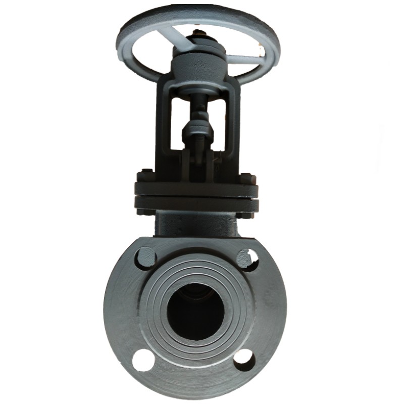
The flanged check valve is a critical component in fluid handling systems, designed to prevent backflow in pipelines. Positioned within the industry chain downstream of valve body casting/forging and upstream of system integration, it ensures unidirectional flow, safeguarding pumps, compressors, and other sensitive equipment from damage or inefficiencies. Flanged connections provide robust and reliable sealing, making these valves suitable for high-pressure and high-temperature applications across diverse sectors, including petrochemicals, power generation, water treatment, and marine engineering. Core performance characteristics center on minimizing pressure drop, maintaining leak-tight shutoff, and exhibiting durability under cyclical operation. A primary industry pain point lies in selecting materials compatible with aggressive fluids while also addressing concerns of valve weight, installation complexity, and long-term maintenance costs. The effective application of flanged check valves relies on a thorough understanding of fluid dynamics, material properties, and industry-specific compliance requirements.
Material Science & Manufacturing
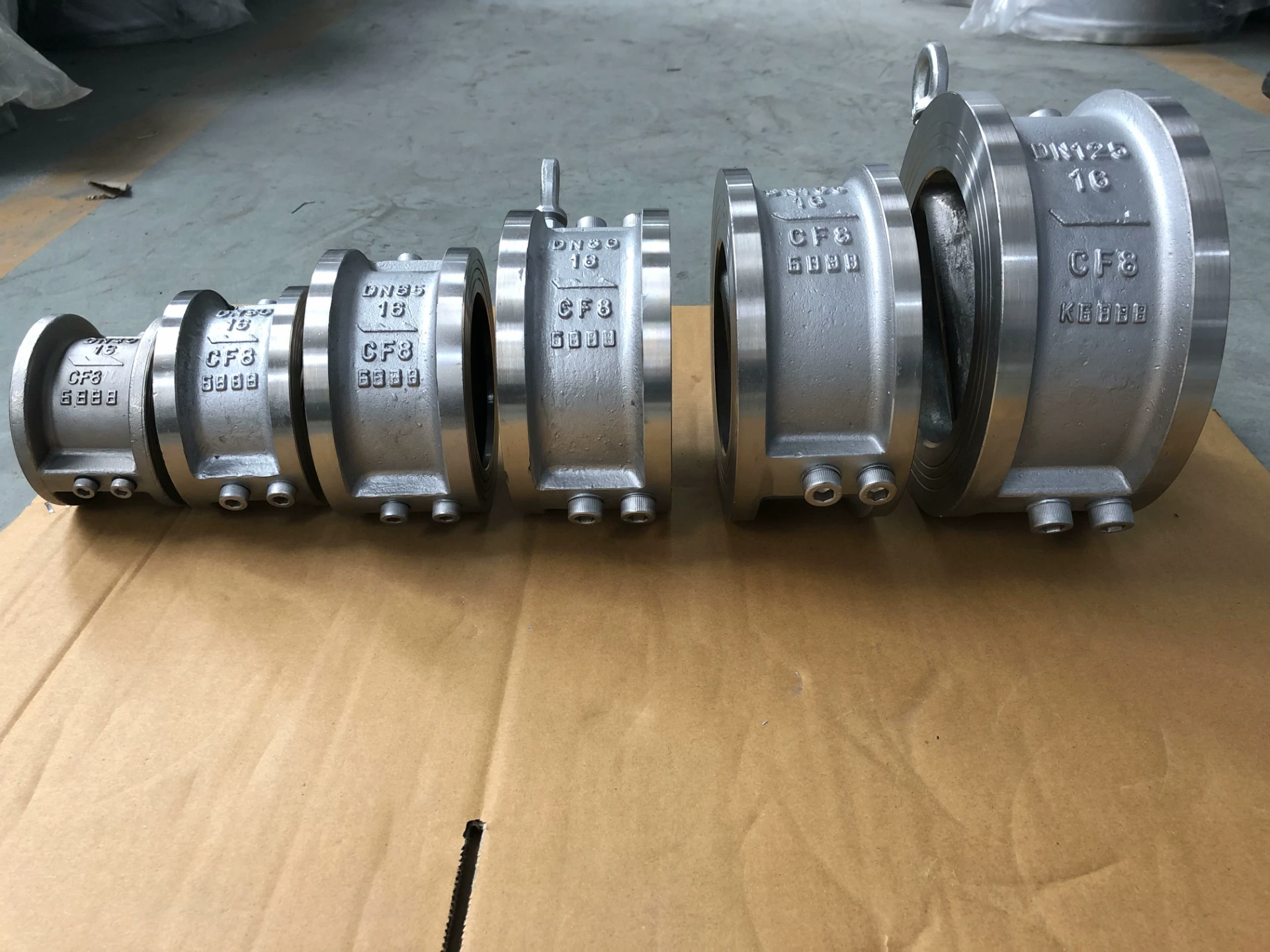
Flanged check valves are constructed from a variety of materials, the choice dictated by the fluid handled, operating temperature, and pressure requirements. Common materials include carbon steel (ASTM A105, A36), stainless steel (304, 316, duplex stainless steels), ductile iron (ASTM A536), and alloy steels (e.g., Chrome-Moly steels). Carbon steel provides cost-effectiveness and strength for general applications, while stainless steel offers superior corrosion resistance in harsh environments. Ductile iron is preferred for its shock resistance and lower cost compared to stainless steel. The manufacturing process typically involves several stages. The valve body is often produced via sand casting, investment casting, or forging. Following body creation, machining operations (CNC turning, milling) ensure dimensional accuracy and smooth sealing surfaces. The disc, responsible for backflow prevention, is often made from a similar material as the body and undergoes precision grinding. Flanged connections are created via bolting, requiring accurate drilling and tapping. Critical parameters controlled during manufacturing include material composition verification (spectrometry), non-destructive testing (NDT) – radiography, ultrasonic testing, liquid penetrant inspection – to detect internal flaws, and dimensional inspections utilizing coordinate measuring machines (CMM). Surface treatments such as epoxy coating or galvanizing are applied to enhance corrosion resistance. Welding processes (SMAW, GTAW) are utilized for specific components and require qualified welders and adherence to ASME Section IX standards. Proper heat treatment after welding is crucial to maintain material integrity and prevent cracking.
Performance & Engineering
The performance of a flanged check valve hinges on its ability to minimize pressure loss and provide a leak-tight seal. Flow coefficient (Cv) is a key parameter, reflecting the valve's capacity to handle fluid flow at a given pressure drop. Force analysis is essential to determine the disc's ability to withstand hydrodynamic forces and prevent chattering. Finite Element Analysis (FEA) is often employed to model stress distribution within the valve body under varying pressure and temperature conditions. Environmental resistance is paramount; prolonged exposure to corrosive fluids can lead to pitting corrosion, crevice corrosion, and ultimately, valve failure. The selection of appropriate gasket materials (e.g., PTFE, EPDM, Viton) is crucial for maintaining seal integrity. Compliance requirements vary by industry and geography. For example, pressure vessel directives (PED – Pressure Equipment Directive in Europe) and ASME Boiler and Pressure Vessel Code (BPVC) in the United States dictate design, fabrication, and testing standards. Functional implementation considerations include valve orientation (horizontal or vertical), upstream and downstream piping configuration, and the potential for water hammer. Swing check valves, characterized by a hinged disc, are suitable for low-to-moderate flow velocities, while lift check valves, with a vertically moving disc, are better suited for high-velocity flows and slurries. The spring return mechanism in certain designs ensures positive disc closure, even under low or reversed flow conditions.
Technical Specifications
| Parameter | Units | Typical Range (Carbon Steel) | Typical Range (Stainless Steel 316) |
|---|---|---|---|
| Maximum Operating Pressure | psi | Up to 2500 | Up to 1500 |
| Maximum Operating Temperature | °F | -20 to 450 | -328 to 650 |
| Connection Type | - | Raised Face, Flat Face | Raised Face, Flat Face |
| Flange Standard | - | ASME B16.5, EN 1092-1 | ASME B16.5, EN 1092-1 |
| Material - Body | - | ASTM A105 / A36 | ASTM A351 CF8M |
| Material - Disc | - | ASTM A105 / A36 | ASTM A351 CF8M |
Failure Mode & Maintenance
Flanged check valves are susceptible to several failure modes. Fatigue cracking can occur in the valve body and disc due to cyclical loading and pressure fluctuations. Corrosion, particularly pitting and crevice corrosion, can weaken the valve components, leading to leakage. Erosion, caused by abrasive particles in the fluid, can damage the disc and sealing surfaces. Disc binding, resulting from debris accumulation or misalignment, can prevent proper closure. Gasket failure, due to material degradation or improper installation, is a common cause of leakage. Cavitation, the formation and implosion of vapor bubbles, can erode the disc and valve body, particularly at high flow velocities. Maintenance strategies include regular visual inspections for corrosion, erosion, and leakage. Periodic testing of the valve’s seat leakage (bubble test) is recommended. Lubrication of the disc hinge (for swing check valves) can prevent binding. Replacement of gaskets and worn components is essential. Non-destructive testing (NDT) should be performed periodically to detect internal flaws. Proper cleaning procedures should be employed to remove debris and prevent clogging. In case of severe corrosion, consider utilizing corrosion inhibitors or upgrading to a more corrosion-resistant material. Adhering to a preventative maintenance schedule based on operating conditions and fluid properties is crucial for maximizing valve lifespan and minimizing downtime.
Industry FAQ
Q: What is the primary difference between a swing check valve and a lift check valve, and how does this affect selection?
A: Swing check valves utilize a hinged disc that swings open with flow and closes due to gravity and backflow. They excel in low to moderate velocity applications and are generally more economical. Lift check valves employ a disc that moves vertically, offering lower pressure drop and superior performance in high-velocity flows and with fluids containing solids. The selection depends heavily on the flow characteristics and fluid composition. For clean fluids and lower velocities, a swing check valve may suffice; for abrasive fluids or high-velocity applications, a lift check valve is preferable.
Q: How do I determine the appropriate gasket material for a specific fluid?
A: Gasket material selection is critical for preventing leakage and ensuring valve longevity. Consult chemical compatibility charts to verify the gasket's resistance to the fluid's chemical composition, concentration, and temperature. Common materials include PTFE (excellent chemical resistance, wide temperature range), EPDM (good resistance to water, steam, and dilute acids), Viton (superior resistance to oils, fuels, and high temperatures), and graphite (high-temperature applications). Consider the fluid’s pH and the potential for swelling or degradation of the gasket material.
Q: What are the potential consequences of water hammer, and how can a check valve mitigate this?
A: Water hammer is a pressure surge caused by a sudden change in flow velocity, often resulting from rapid valve closure. It can cause significant damage to pipelines, pumps, and valves. Check valves, by preventing backflow, help to dampen the impact of water hammer. Slow-closing check valves or those with dampening mechanisms further reduce the severity of pressure surges.
Q: How important is Non-Destructive Testing (NDT) during the manufacturing process?
A: NDT is crucial for identifying internal flaws, such as cracks, porosity, or inclusions, that are not visible to the naked eye. Radiographic testing (RT), ultrasonic testing (UT), and liquid penetrant inspection (LPI) are commonly employed. These methods ensure the structural integrity of the valve body and disc, preventing premature failure and ensuring safe operation. Adherence to ASME standards for NDT procedures is paramount.
Q: What factors influence the pressure drop across a flanged check valve?
A: Pressure drop is affected by flow rate, valve size, valve type (swing vs. lift), and the fluid's viscosity. Larger valve sizes and streamlined designs minimize pressure drop. Lift check valves generally offer lower pressure drop compared to swing check valves at equivalent flow rates. Proper valve sizing, based on anticipated flow conditions, is crucial for minimizing energy losses.
Conclusion
The flanged check valve remains an indispensable component in a wide range of industrial fluid handling applications. Its selection and proper implementation are dictated by a nuanced understanding of material science, fluid dynamics, and applicable industry standards. Addressing key pain points, such as material compatibility, pressure drop minimization, and long-term reliability, requires diligent attention to manufacturing processes, rigorous quality control, and proactive maintenance strategies.
Future advancements in check valve technology are likely to focus on the development of lightweight materials, intelligent valve designs with integrated sensors for performance monitoring, and optimized flow paths to further reduce pressure loss. By embracing these innovations, engineers can enhance the efficiency, safety, and longevity of fluid handling systems.
-
Top Reasons to Choose a Stainless Steel Flange Check Valve for Industrial Applications
-
8 inch flange Performance Analysis
-
angle ring flanges Performance Analysis
-
Flat Flanges Performance Analysis
-
Full Face Flange Performance Analysis
-
Full Face Flanges Performance Analysis
-
flange 8 inch Performance Analysis
-
Ring Flange Performance Analysis
-
3 inch split flange Performance Analysis
-
Tongue and groove flange Performance Analysis
-
Grooved Flange Performance Analysis
-
o ring flange Performance Analysis
-
Ring Flanges Performance Analysis
-
Groove Flange Performance Analysis
-
Tongue and groove flanges Performance Analysis