


globe valve Performance Engineering
Introduction
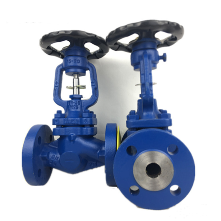
The globe valve is a type of valve used to regulate flow. Distinguished by its spherical body and internal baffle, it offers precise throttling capabilities, unlike gate valves optimized for on/off service. Positioned within the fluid control industry, globe valves serve critical roles in power generation, chemical processing, oil and gas refining, and district heating/cooling systems. Their primary performance characteristic is modulating flow, achieving accurate control through variable positioning of the disc relative to the seat. Core to their function is minimizing pressure drop during throttling, and efficient shutoff when fully closed. Industry pain points center around erosion of valve internals due to high-velocity flow, fugitive emissions related to stem packing and seat sealing, and the complexity of maintaining tight shutoff in challenging process conditions. Addressing these requires advanced materials, precise machining, and robust sealing technologies.
Material Science & Manufacturing
Globe valve construction typically employs materials like cast iron (ASTM A126 Grade B for general service), carbon steel (ASTM A105 for higher temperatures and pressures), stainless steel (304/316 – ASTM A351 Grade CF8/CF8M for corrosive environments), and alloy steels (ASTM A182 F22 for cryogenic applications). The choice depends heavily on the fluid being controlled and operational parameters. Body manufacturing commonly involves sand casting or investment casting, followed by extensive machining to achieve dimensional accuracy and smooth surface finishes essential for sealing. Discs are forged or cast, heat-treated for hardness and wear resistance, and lapped to ensure tight shutoff. Stems are typically machined from bar stock, utilizing materials compatible with the body and disc. Seat rings are often made from reinforced PTFE (Teflon), metal alloys (Hastelloy, Stellite) or ceramic materials. Welding procedures (AWS D1.1) are critical for joining valve components, requiring qualified welders and stringent inspection to prevent porosity or cracking. Parameter control during heat treatment – including temperature, soaking time, and cooling rates – directly impacts the material's mechanical properties and long-term reliability. Stem packing, utilizing materials like graphite or PTFE with specialized fillers, requires precise compression to prevent leakage without inducing excessive friction.
Performance & Engineering
Globe valve performance hinges on several key engineering principles. Flow analysis, utilizing Computational Fluid Dynamics (CFD), is vital to optimize valve geometry, minimizing turbulence and cavitation, which can cause erosion and noise. Force analysis considers hydrostatic forces, fluid dynamic forces, and thermal stresses acting on the disc and stem, informing material selection and component sizing. Environmental resistance is a major concern. Valves exposed to corrosive fluids must be constructed from resistant alloys or coated with protective layers (epoxy, PTFE). High-temperature applications necessitate designs that accommodate thermal expansion and contraction to maintain sealing integrity. Compliance with standards like ANSI/FCI 70-2 governs pressure-temperature ratings and testing procedures. The valve’s Kv (flow coefficient) and Cv (flow capacity) are critical parameters determining flow rate versus pressure drop. Actuator selection (pneumatic, electric, hydraulic) dictates responsiveness and control accuracy. The stem packing design must account for pressure and temperature variations to prevent fugitive emissions, complying with EPA standards. Furthermore, understanding the inherent limitations of globe valves—namely, higher pressure drop compared to gate valves—is critical for proper system integration.
Technical Specifications
| Parameter | Unit | Typical Value (Carbon Steel) | Typical Value (Stainless Steel 316) |
|---|---|---|---|
| Maximum Operating Pressure | psi | 900 | 650 |
| Maximum Operating Temperature | °F | 800 | 600 |
| Connection Type | - | Screwed, Flanged, Welded | Screwed, Flanged, Welded |
| Body Material | - | Carbon Steel (ASTM A105) | Stainless Steel 316 (ASTM A351 CF8M) |
| Disc Material | - | Carbon Steel, Alloy Steel | Stainless Steel 316 |
| Seat Material | - | Reinforced PTFE | Reinforced PTFE |
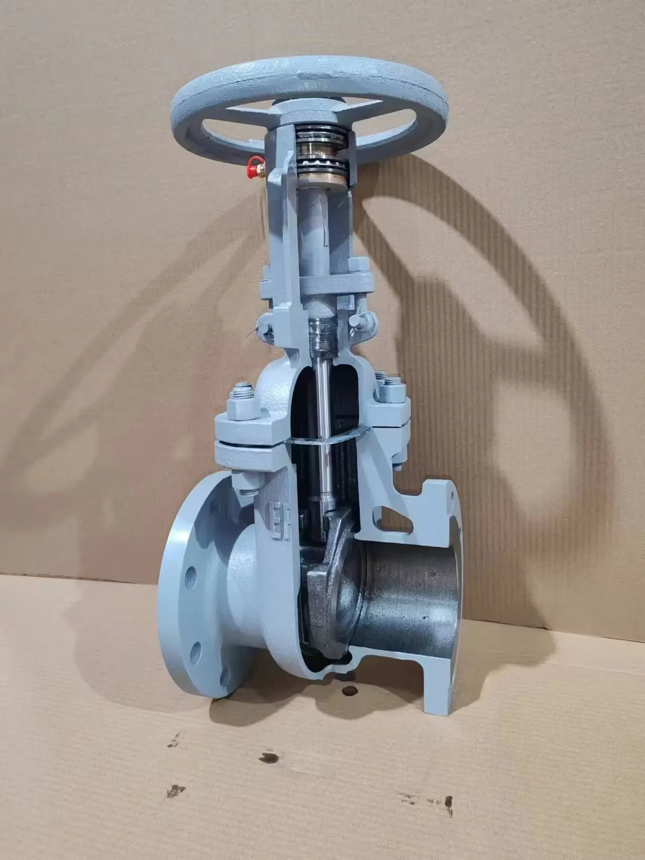
Failure Mode & Maintenance
Globe valve failures commonly arise from several modes. Erosion, particularly in high-velocity flow applications, wears down the disc and seat, leading to leakage. Cavitation, caused by pressure drops, creates imploding bubbles that damage valve internals. Corrosion, especially in aggressive fluids, degrades the body and disc materials. Fatigue cracking, resulting from repeated stress cycles, can occur in the stem or disc. Stem packing failure leads to fugitive emissions. Failure analysis often reveals root causes related to improper material selection, inadequate maintenance, or exceeding operational limits. Preventive maintenance is crucial, including regular inspection of packing glands, disc and seat condition, and actuator functionality. Periodic back-seating of the disc helps maintain sealing integrity. Lubrication of the stem threads reduces friction and prevents galling. Non-destructive testing (NDT) methods like ultrasonic testing or radiographic inspection can identify internal flaws. Replacement of worn or corroded components is essential. Scheduled overhauls, typically every 1-3 years depending on service conditions, ensure long-term reliability and safety.
Industry FAQ
Q: What are the key differences between a globe valve and a gate valve in terms of application?
A: Gate valves are designed for fully open or fully closed service, offering minimal pressure drop when open. They are not suitable for throttling. Globe valves, conversely, excel at modulating flow and precise control, but introduce a higher pressure drop. Choose gate valves for on/off isolation and globe valves for regulating flow.
Q: How does material selection impact the longevity of a globe valve in corrosive environments?
A: In corrosive environments, selecting materials resistant to the specific fluid is paramount. Stainless steel alloys (316, Hastelloy) and specialized coatings (PTFE, epoxy) provide protection against chemical attack. Improper material selection leads to rapid degradation and premature failure.
Q: What are the implications of cavitation on globe valve performance?
A: Cavitation causes severe damage to the disc and seat, leading to erosion, noise, and reduced valve life. Mitigation strategies include optimizing valve geometry to reduce pressure drop, using cavitation-resistant materials, and ensuring adequate upstream pressure.
Q: What type of maintenance schedule is recommended for globe valves in critical applications?
A: A preventative maintenance schedule should include monthly visual inspections, quarterly packing gland adjustments, annual disc and seat inspections (with potential lapping), and 3-5 year overhauls with component replacement as needed. Record keeping is crucial.
Q: How do different actuator types (pneumatic, electric, hydraulic) affect the precision and response time of a globe valve?
A: Pneumatic actuators offer fast response times and are suitable for applications requiring quick adjustments. Electric actuators provide precise positioning and are often used in automated control systems. Hydraulic actuators offer high force and are ideal for large, high-pressure valves, but typically have slower response times.
Conclusion
Globe valves remain essential components in numerous industrial processes requiring precise flow control. Their performance and longevity are fundamentally linked to meticulous material selection, robust manufacturing processes, and diligent maintenance protocols. Understanding the nuances of fluid dynamics, corrosion mechanisms, and failure modes is critical for ensuring reliable operation and minimizing downtime.
Future advancements in globe valve technology are focusing on developing advanced materials with enhanced erosion and corrosion resistance, implementing intelligent diagnostic systems for predictive maintenance, and optimizing valve designs for reduced pressure drop and improved energy efficiency. Continued adherence to industry standards and best practices will solidify the globe valve’s position as a cornerstone of fluid control systems.
-
Top Reasons to Choose a Stainless Steel Flange Check Valve for Industrial Applications
-
8 inch flange Performance Analysis
-
angle ring flanges Performance Analysis
-
Flat Flanges Performance Analysis
-
Full Face Flange Performance Analysis
-
Full Face Flanges Performance Analysis
-
flange 8 inch Performance Analysis
-
Ring Flange Performance Analysis
-
3 inch split flange Performance Analysis
-
Tongue and groove flange Performance Analysis
-
Grooved Flange Performance Analysis
-
o ring flange Performance Analysis
-
Ring Flanges Performance Analysis
-
Groove Flange Performance Analysis
-
Tongue and groove flanges Performance Analysis