


pilot check valves Performance Analysis
Introduction
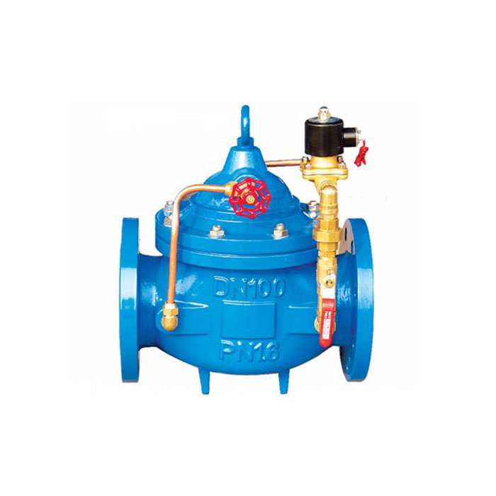
Pilot check valves are critical components in fluid power systems, functioning as unidirectional flow control devices. Unlike conventional check valves relying solely on spring force or gravity, pilot-operated check valves utilize a pilot pressure signal to allow flow in one direction while preventing reverse flow. These valves are strategically positioned within hydraulic circuits to prevent backflow, maintain system pressure, and protect sensitive components such as pumps and actuators. Their application spans a wide array of industries including oil & gas, aerospace, marine, and heavy machinery. A key industry pain point centers around ensuring consistent and reliable operation under varying pressure and temperature conditions, particularly in high-performance hydraulic applications where even momentary backflow can lead to system instability or damage. The performance is characterized by cracking pressure, flow capacity (Cv), leakage rate, and response time, all crucial parameters for system integration and efficiency. Pilot-operated designs address limitations of traditional check valves when handling high flow rates and low pressure differentials.
Material Science & Manufacturing
The body of a pilot check valve is commonly manufactured from carbon steel (AISI 1045, yield strength >360 MPa) for high-pressure applications, or 316 stainless steel for corrosive environments. Material selection prioritizes tensile strength, fatigue resistance, and compatibility with the working fluid. Internal components, such as poppets and seats, are often constructed from hardened tool steels (e.g., D2, HRC 60-65) to withstand repeated impact and abrasion. Seals are typically made from Nitrile (Buna-N) for mineral oil-based hydraulic fluids, Viton (FKM) for high-temperature or phosphate ester fluids, or PTFE for aggressive chemical compatibility. The manufacturing process generally involves precision machining of valve body components, followed by heat treatment to achieve desired hardness and surface finish. Critical dimensions, such as orifice diameter and seat geometry, are tightly controlled using CNC machining and coordinate measuring machines (CMM). Welding processes, when employed for fabrication, must adhere to standards like AWS D1.1 to ensure structural integrity. The pilot valve itself, often a small solenoid valve integrated within the check valve housing, employs a similar manufacturing approach, with focus on coil winding precision and electrical insulation. Surface treatments such as nitriding or chrome plating are frequently used to enhance wear resistance and corrosion protection. The chemical compatibility of all materials with the intended fluid is a critical parameter; incompatibility can lead to swelling, degradation of seals, and ultimately, valve failure.

Performance & Engineering
The performance of a pilot check valve is governed by several key engineering principles. The cracking pressure, the minimum upstream pressure required to initiate flow, is determined by the spring force acting on the poppet and the effective area of the poppet. Flow capacity (Cv) is a measure of the valve’s ability to pass fluid, directly impacting system response time. Leakage rate, measured in milliliters per minute, quantifies the amount of fluid that bypasses the valve when it’s in the closed position; minimizing leakage is crucial for maintaining system pressure and efficiency. Response time, the time taken for the valve to fully open or close, affects system stability and control accuracy. Force analysis is crucial in designing the valve, ensuring the poppet can withstand the maximum system pressure without deformation or failure. Environmental resistance is addressed through material selection and sealing design, accommodating temperature variations (-40°C to 120°C typical) and exposure to contaminants. Compliance requirements vary by industry; for example, aerospace applications demand adherence to MIL-STD-810G for shock and vibration testing, while applications in hazardous environments require ATEX certification for explosion protection. Furthermore, the valve’s pressure drop characteristics must be modeled to optimize system efficiency. Computational Fluid Dynamics (CFD) is frequently used to simulate flow patterns and identify potential cavitation or erosion issues.
Technical Specifications
| Parameter | Metric Units | Imperial Units | Typical Range |
|---|---|---|---|
| Maximum Pressure | MPa | PSI | 70 - 350 |
| Flow Capacity (Cv) | m³/h | GPM | 0.5 - 10 |
| Cracking Pressure | MPa | PSI | 0.3 - 10 |
| Leakage Rate | mL/min | oz/min | < 0.1 |
| Operating Temperature | °C | °F | -40 to 120 |
| Port Size | mm | inches | 1/4, 3/8, 1/2 |
Failure Mode & Maintenance
Pilot check valves are susceptible to several failure modes. Fatigue cracking of the poppet or seat can occur due to repeated stress cycles under high pressure. Erosion of the seat surface, caused by abrasive particles in the fluid, leads to increased leakage. Seal degradation (swelling, cracking, or hardening) results in bypass flow and reduced holding pressure. Contamination, particularly metallic debris, can obstruct the pilot valve, preventing it from shifting and leading to complete valve blockage. Cavitation, caused by rapid pressure fluctuations, can erode valve components. A common failure is the sticking of the pilot valve spool due to varnish build-up from fluid degradation. Preventative maintenance involves regular fluid filtration to remove contaminants, periodic inspection of seals for wear or damage, and functional testing to verify cracking pressure and leakage rate. If a valve fails to operate correctly, disassembly and inspection are required to identify the root cause. Damaged seals should be replaced with compatible materials. Thorough cleaning of all components is essential prior to reassembly. Regular monitoring of system pressure and temperature can help identify potential issues before they lead to catastrophic failure. Proper storage of spare valves is crucial; they should be capped to prevent contamination and stored in a dry environment.
Industry FAQ
Q: What is the impact of fluid viscosity on the cracking pressure of a pilot check valve?
A: Increased fluid viscosity raises the cracking pressure. The higher resistance to flow requires a greater pressure differential to overcome the spring force and initiate valve opening. This relationship is non-linear, and valve selection must account for the viscosity range of the operating fluid.
Q: How does temperature affect the leakage rate of a pilot check valve?
A: Elevated temperatures typically increase leakage rate due to thermal expansion of valve components and softening of seals. Conversely, low temperatures can cause seals to become brittle and also increase leakage. The seal material must be compatible with the operating temperature range.
Q: What are the critical considerations when selecting a pilot check valve for a high-frequency cycling application?
A: For high-frequency cycling, fatigue resistance of the poppet and seat becomes paramount. Valves with hardened components and optimized geometries are essential. Response time is also critical to ensure the valve can keep pace with the cycling rate without compromising performance.
Q: Can pilot check valves be used with fluids containing particulate matter? If so, what precautions should be taken?
A: While pilot check valves can tolerate some particulate matter, excessive contamination significantly reduces valve life. Inline filtration is essential. Furthermore, valves with hardened seats and wider flow passages are more resistant to abrasion. Regular filter maintenance is critical.
Q: What is the role of the pilot valve within the check valve assembly, and what happens if the pilot valve fails?
A: The pilot valve controls the release of pressure, allowing the main poppet to open against its spring force. If the pilot valve fails in the closed position, the check valve effectively becomes a standard, spring-loaded check valve. If the pilot valve fails open, the check valve may allow reverse flow, potentially damaging the system.
Conclusion
Pilot check valves represent a significant advancement in unidirectional flow control technology, offering superior performance compared to traditional designs, especially in high-pressure, high-flow applications. Their reliance on pilot pressure allows for precise control and reduced cracking pressures, addressing a core industry need for reliable backflow prevention. Material selection and manufacturing processes are intrinsically linked to valve performance and longevity, demanding rigorous quality control and adherence to industry standards.
Future development trends will likely focus on miniaturization, improved seal materials with enhanced temperature and chemical resistance, and integration of smart sensors for real-time performance monitoring and predictive maintenance. Understanding the nuances of failure modes and implementing proactive maintenance strategies are crucial for maximizing valve lifespan and ensuring the integrity of hydraulic systems. Selecting the appropriate pilot check valve requires careful consideration of application-specific parameters, including fluid type, pressure, temperature, and flow rate.
-
Top Reasons to Choose a Stainless Steel Flange Check Valve for Industrial Applications
-
check valve 3 4 inch Performance Analysis
-
3 4 inch check valve Performance Analysis
-
piloted check valve Performance Analysis
-
pilot check valves Performance Analysis
-
low pressure check valve Performance Analysis
-
check valves high pressure Performance Analysis
-
check valves low pressure Performance Analysis
-
High Pressure Check Valves Performance Analysis
-
low pressure check valves Performance Analysis
-
6 check valve Performance Analysis
-
stainless steel check valves Performance Analysis
-
check valve 6 Performance Analysis
-
check valve stainless steel Performance Analysis
-
6 in check valve Performance Engineering