




Pinion Flange Performance Analysis

Introduction
The pinion flange is a critical mechanical component employed in power transmission systems, primarily connecting a pinion shaft to a larger rotating element like a gear or drum. Functionally, it acts as a torque transfer interface, adapting the rotational force from the pinion to the driven component. Its technical position within the industrial chain falls between the gear manufacturing process and the final assembly of larger machinery, commonly found in automotive differentials, industrial gearboxes, and wind turbine systems. Core performance characteristics are defined by its torque capacity, torsional stiffness, and ability to withstand dynamic loading and environmental factors. Proper flange design and material selection are paramount for preventing failure and ensuring the longevity of the overall system. The challenges faced by industries relying on pinion flanges include minimizing backlash, reducing weight, and maximizing fatigue life under demanding operating conditions. Selecting the correct flange, considering its material, dimensions, and mounting configuration, directly impacts system efficiency and reliability.
Material Science & Manufacturing
Pinion flanges are commonly manufactured from medium to high carbon steels (e.g., 4140, 8620) due to their excellent strength, ductility, and machinability. Alloy steels containing chromium, molybdenum, and nickel are also frequently employed to enhance hardenability, toughness, and resistance to wear. The raw material undergoes rigorous quality control, including chemical composition analysis and non-destructive testing (NDT) like ultrasonic inspection, to verify its integrity. Manufacturing processes depend on the flange’s complexity and production volume. Forging is preferred for high-strength applications, offering superior grain structure and impact resistance. Machining, including turning, milling, and drilling, refines the forged blank to the desired dimensions and tolerances. Critical parameters during machining include cutting speed, feed rate, and coolant application to prevent thermal distortion and maintain dimensional accuracy. Welding is often used to attach reinforcing features or mounting brackets. Welding procedures must be carefully controlled, using appropriate filler metals and heat treatment cycles, to avoid weld defects like porosity, cracking, and distortion. Surface treatments like heat treatment (hardening, tempering) and coating (phosphate, zinc plating) are applied to improve wear resistance, corrosion protection, and fatigue life. Precise dimensional control, particularly for bolt hole patterns and runout, is crucial for ensuring proper alignment and torque transfer in the assembled system. Material certifications, including mill test reports, are essential for traceability and compliance with industry standards.
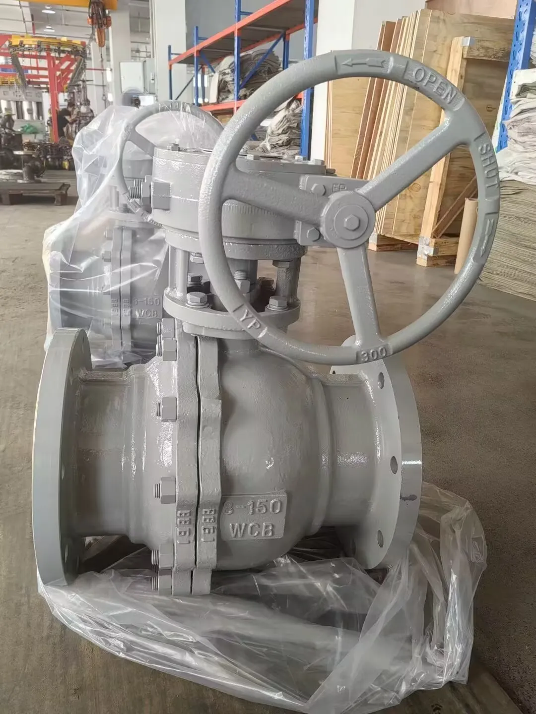
Performance & Engineering
The performance of a pinion flange is governed by several key engineering principles. Torsional stress analysis is critical to determine the flange's ability to transmit torque without yielding or fracturing. Finite element analysis (FEA) is routinely employed to simulate stress distribution under various loading conditions, including static torque, dynamic torque, and impact loads. Backlash, the amount of play between mating components, is a critical performance parameter. Excessive backlash can lead to noise, vibration, and reduced efficiency. Flange design must minimize backlash through precise manufacturing tolerances and preloading techniques. Environmental resistance is also a significant consideration, particularly in applications exposed to corrosive environments or extreme temperatures. Material selection and surface coatings must provide adequate protection against corrosion, oxidation, and degradation. Compliance with industry standards, such as those defined by the American Gear Manufacturers Association (AGMA) and the Society of Automotive Engineers (SAE), is essential. These standards specify requirements for material properties, dimensional tolerances, and testing procedures. Fatigue life is a paramount concern, as pinion flanges are subjected to cyclic loading. Fatigue analysis, based on S-N curves and fracture mechanics principles, is used to predict the flange’s service life. The mounting configuration of the flange, including the number and size of bolts, significantly affects its performance. Proper bolt tightening torque and bolt preload are crucial for maintaining clamping force and preventing loosening. Force analysis involves evaluating the shear and tensile forces acting on the bolts and the flange material, ensuring they remain within acceptable limits.
Technical Specifications
| Parameter | Typical Value (Steel Alloy 4140) | Unit | Testing Standard |
|---|---|---|---|
| Yield Strength | 655 | MPa | ASTM A370 |
| Tensile Strength | 760 | MPa | ASTM A370 |
| Hardness (Rockwell C) | 25-35 | HRC | ASTM A388 |
| Maximum Torque Capacity | 500 - 5000 | Nm | Calculated per AGMA 925 |
| Bolt Hole Diameter | 12 - 30 | mm | DIN 976 / ISO 4762 |
| Backlash (Maximum) | 0.05 - 0.1 | mm | Manufacturer Specification |
Failure Mode & Maintenance
Pinion flanges are susceptible to several failure modes. Fatigue cracking is a common failure mechanism, initiated by cyclic loading and stress concentrations at bolt holes or keyways. Corrosion pitting can also initiate cracks, particularly in harsh environments. Shear failure of the flange material can occur if the torque exceeds the flange’s capacity. Weld defects, such as porosity or incomplete fusion, can create stress raisers and lead to premature failure. Delamination of surface coatings can reduce corrosion resistance and accelerate degradation. Regular maintenance is crucial for preventing failures. Visual inspection for cracks, corrosion, and deformation should be performed periodically. Torque checks on mounting bolts are essential to ensure proper clamping force. Lubrication of mating surfaces reduces friction and wear. Non-destructive testing (NDT) techniques, such as dye penetrant inspection or magnetic particle inspection, can detect surface cracks that are not visible to the naked eye. If cracks are detected, the flange should be removed from service and repaired or replaced. Proper storage conditions, protected from moisture and corrosive agents, are essential for extending the flange’s service life. Record-keeping of inspection and maintenance activities is vital for tracking performance and identifying potential problems. Periodic analysis of failed flanges can provide valuable insights into root causes and prevent future occurrences.
Industry FAQ
Q: What is the impact of flange runout on gearbox performance?
A: Excessive flange runout introduces misalignment in the power transmission system, leading to increased vibration, noise, and premature wear of gears and bearings. Runout exceeding specified tolerances can significantly reduce gearbox efficiency and lifespan. Precision machining and careful alignment procedures are essential for minimizing runout.
Q: How does material selection affect the fatigue life of a pinion flange?
A: Material properties, such as yield strength, tensile strength, and ductility, directly influence fatigue life. Higher strength materials generally exhibit improved fatigue resistance. However, material toughness is also critical, as brittle materials are more susceptible to crack initiation and propagation. Proper heat treatment and surface finishing can further enhance fatigue performance.
Q: What are the considerations when selecting a flange coating for corrosive environments?
A: The choice of coating depends on the specific corrosive agent and operating temperature. Zinc plating provides good corrosion protection in mild environments. Phosphate coatings enhance paint adhesion and provide limited corrosion resistance. More aggressive environments may require specialized coatings, such as epoxy coatings, ceramic coatings, or stainless steel cladding.
Q: What is the role of bolt preload in maintaining flange integrity?
A: Bolt preload creates a clamping force that compresses the mating surfaces, increasing friction and preventing loosening. Proper preload also distributes the load more evenly across the flange, reducing stress concentrations. Insufficient preload can lead to bolt loosening and flange separation, while excessive preload can cause bolt yielding or flange distortion.
Q: How can Finite Element Analysis (FEA) be used to optimize pinion flange design?
A: FEA allows engineers to simulate stress distribution under various loading conditions, identify potential failure points, and optimize the flange geometry and material selection. FEA can be used to minimize weight, maximize strength, and improve fatigue life. It is also crucial for validating the design against industry standards and safety factors.
Conclusion
The pinion flange, despite its seemingly simple design, is a critical component in numerous power transmission systems. Its performance directly impacts the efficiency, reliability, and longevity of the overall machinery. Understanding the material science, manufacturing processes, and engineering principles governing flange behavior is essential for ensuring optimal performance. Careful attention to design details, material selection, and manufacturing tolerances is crucial for preventing failures and maximizing service life.
Continued advancements in materials science, manufacturing techniques, and simulation tools will further enhance the performance and durability of pinion flanges. The increasing demand for lightweight and high-performance components will drive the development of new materials and designs. Rigorous adherence to industry standards and best practices remains paramount for ensuring the safety and reliability of these critical components.
-
Top Reasons to Choose a Stainless Steel Flange Check Valve for Industrial Applications
-
Flange Square Performance Analysis
-
flanged butterfly valve Performance Analysis
-
flanged gate valve Material Science Manufacturing
-
Pinion Flange Performance Analysis
-
Precision flange Performance Analysis
-
Stub End Flange Performance Analysis
-
Turbo Exhaust Flange Material Analysis
-
Shaft collar flange Performance Analysis
-
butterfly valve flanged Performance Analysis
-
flange butterfly valves Performance Engineering
-
flanged butterfly valves Performance Analysis
-
flanged gate valves Performance Analysis
-
Flanges for butterfly valves Material Analysis
-
gate valve flange Performance Analysis
 Afrikaans
 Albanian
 Amharic
 Arabic
 Armenian
 Azerbaijani
 Basque
 Belarusian
 Bengali
 Bosnian
 Bulgarian
 Catalan
 Cebuano
 Corsican
 Croatian
 Czech
Czech
 Danish
 Dutch
Dutch
 Esperanto
 Estonian
 Finnish
 French
 Frisian
 Galician
 Georgian
 German
 Greek
Greek
 Gujarati
 Haitian Creole
 Hausa
Hawaiian
Hausa
Hawaiian
 Hebrew
 Hindi
Hindi
 Miao
Miao
 Hungarian
 Icelandic
 Igbo
Igbo
 Indonesian
 Irish
Irish
 Italian
 Japanese
 Javanese
Kannada
Javanese
Kannada
 Kazakh
 Khmer
Khmer
 Rwandese
 Korean
 Kurdish
 Kyrgyz
 Lao
Lao
 Latin
Latin
 Latvian
 Lithuanian
 Luxembourgish
 Macedonian
 Malgashi
 Malay
Malay
 Malayalam
 Maltese
 Maori
Maori
 Marathi
 Mongolian
 Myanmar
 Nepali
 Norwegian
 Norwegian
 Occitan
 Pashto
 Persian
 Polish
 Portuguese
Punjabi
Portuguese
Punjabi
 Romanian
 Russian
 Samoan
 Scottish Gaelic
 Serbian
 Sesotho
 Shona
Shona
 Sindhi
 Sinhala
 Slovak
 Slovenian
 Somali
 Spanish
 Sundanese
 Swahili
 Swedish
Tagalog
Swedish
Tagalog
 Tajik
Tajik
 Tamil
Tamil
 Tatar
Tatar
 Telugu
 Thai
Thai
 Turkish
 Turkmen
 Ukrainian
 Urdu
Urdu
 Uighur
 Uzbek
Uzbek
 Vietnamese
 Welsh
Welsh
 Bantu
Bantu
 Yiddish
 Yoruba
 Zulu
Zulu
 English