




flanged gate valves Performance Analysis
Introduction
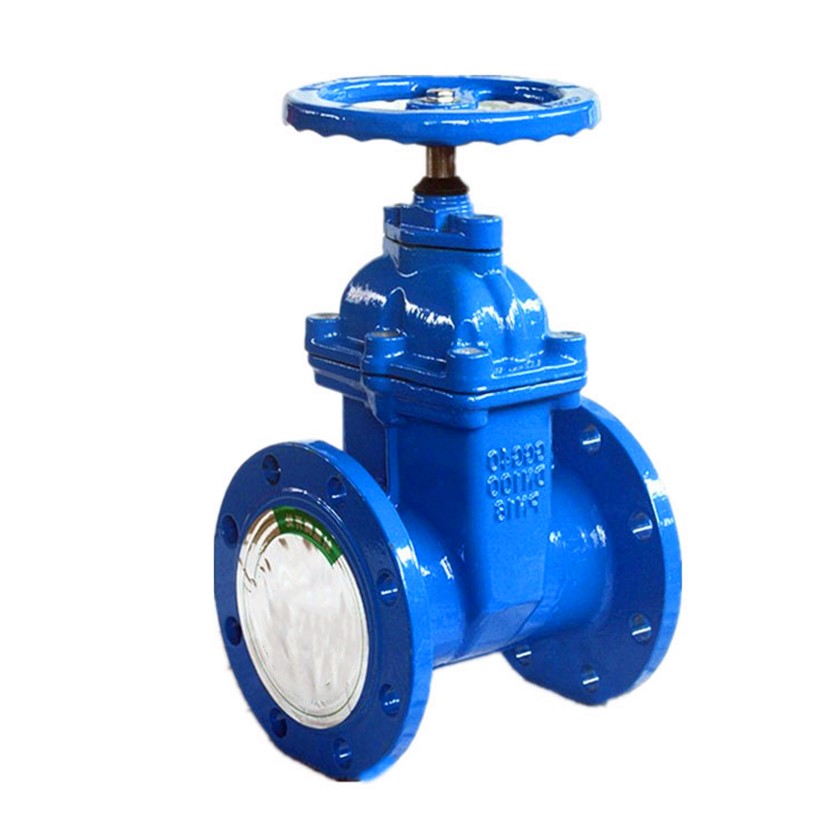
Flanged gate valves are a critical component in fluid handling systems across numerous industries, including oil and gas, water treatment, chemical processing, and power generation. Positioned as a linear motion valve, its primary function is to control the flow of liquids, gases, or slurries by raising or lowering a gate within the flow path. Unlike other valve types, gate valves are typically fully open or fully closed, not designed for throttling applications. The 'flanged' designation refers to the connection method – utilizing bolted flanges to connect the valve to the piping system, providing a robust and leak-proof seal. Their robust construction and relatively low pressure drop when fully open make them ideal for on/off service in large-diameter pipelines. This guide provides an in-depth technical exploration of flanged gate valves, covering material science, manufacturing processes, performance characteristics, failure modes, and relevant industry standards. Core industry pain points addressed include material selection for corrosive environments, ensuring long-term sealing integrity, and mitigating flow-induced vibration and erosion.
Material Science & Manufacturing
The body of a flanged gate valve is commonly constructed from cast iron (ASTM A126 Class B), ductile iron (ASTM A536 65-45-12), carbon steel (ASTM A216 WCB, A105), stainless steel (ASTM A351 Grade CF8, CF8M, CF3, CF3M), or alloy steels (ASTM A182 F11, F22). Material selection is paramount, dictated by the fluid being handled, operating temperature, and pressure requirements. For instance, in seawater applications, stainless steel alloys with high resistance to chloride-induced pitting corrosion are essential. The gate itself is typically made from bronze (B148 C95500), stainless steel, or nickel-based alloys. Seat materials include elastomers (EPDM, NBR, Viton) for low-pressure, low-temperature applications, and metal seats (stainless steel, alloy 400) for high-temperature and high-pressure service. The manufacturing process typically involves casting (for the body), forging (for the stem and wedge), and machining. Critical parameters during manufacturing include ensuring dimensional accuracy of the gate and seat to achieve a bubble-tight shutoff. Welding procedures, particularly for stainless steel components, must adhere to ASME Section IX to maintain corrosion resistance and prevent weld decay. Non-destructive testing (NDT), including radiography and ultrasonic testing, is crucial for verifying weld integrity and detecting internal flaws. Surface treatments, such as epoxy coating or galvanizing, are applied to the exterior of the valve body to provide corrosion protection.
Performance & Engineering
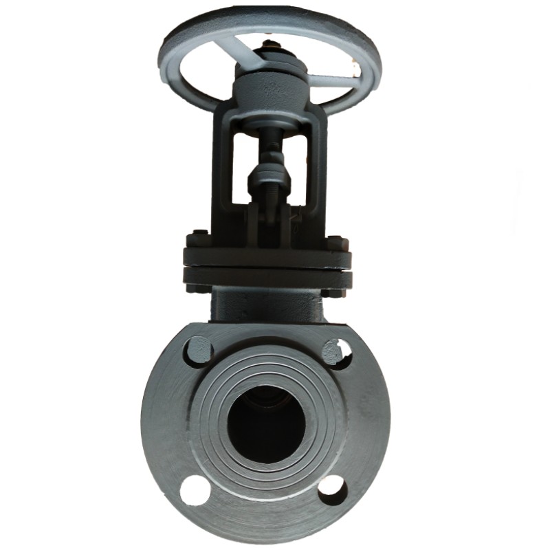
Performance of flanged gate valves is primarily assessed based on their ability to provide a leak-tight seal at the specified pressure and temperature rating. This is evaluated through hydrostatic testing according to API 598, which involves pressurizing the valve with water to 1.5 times the working pressure. Flow characteristics are also important; the coefficient of flow (Cv) determines the valve’s capacity to pass a given flow rate with a specific pressure drop. Force analysis during operation is critical to ensure the stem and gate can withstand the fluid pressure and prevent deformation. Finite element analysis (FEA) is often used to optimize the valve's design and minimize stress concentrations. Environmental resistance is a major concern, particularly in corrosive environments. Material selection and protective coatings must be appropriate for the specific application. Gate valves must also meet relevant compliance requirements, such as those stipulated by the Pressure Equipment Directive (PED) in Europe and ASME Boiler and Pressure Vessel Code Section VIII Division 1 in the United States. Furthermore, considerations regarding fugitive emissions (leakage of process fluids into the atmosphere) are increasingly important, leading to the adoption of low-emission designs and packing materials compliant with EPA Method 21.
Technical Specifications
| Parameter | Specification (Typical) | Unit | Test Standard |
|---|---|---|---|
| Maximum Working Pressure | 150-2500 | psi | ASME B16.34 |
| Operating Temperature Range | -29°C to 427°C | °C | ASTM E203 |
| Body Material | Carbon Steel (A216 WCB), Stainless Steel (A351 CF8) | - | ASTM A193 B8 |
| Seat Material | NBR, EPDM, PTFE, Stainless Steel | - | API 598 |
| Gate Material | Bronze, Stainless Steel | - | ASTM A485 |
| Connection Type | Flanged (ANSI/ASME B16.5) | - | ANSI/ASME B16.5 |
Failure Mode & Maintenance
Common failure modes for flanged gate valves include gate sticking, seat erosion, stem leakage, and flange joint failure. Gate sticking can occur due to corrosion, debris buildup, or insufficient lubrication. Seat erosion is prevalent in high-velocity flow applications, particularly with abrasive fluids. Stem leakage is often caused by worn packing or damage to the stem surface. Flange joint failure can result from improper bolt torque, gasket degradation, or corrosion of the flange faces. Failure analysis techniques, such as metallographic examination and fracture surface analysis, can help determine the root cause of failures. Regular maintenance is crucial for preventing failures and extending the valve's service life. This includes periodic inspection of the valve body, stem, and seat for signs of corrosion or wear. Lubrication of the stem and gate is essential to prevent sticking. Proper bolt torqueing of the flange joints is critical to maintain a leak-tight seal. Regular replacement of the packing and gaskets is also recommended. For critical applications, preventative maintenance programs incorporating ultrasonic testing of the valve body and flanges can detect early signs of corrosion or cracking. Implementing a robust valve management system, tracking maintenance history, and adhering to manufacturer's recommendations are vital for ensuring reliable operation.
Industry FAQ
Q: What are the key considerations when selecting a gate valve material for a high-temperature, high-pressure steam application?
A: For high-temperature, high-pressure steam, alloy steel materials like ASTM A182 F22 (15CrMoV) are preferred due to their excellent creep resistance and oxidation resistance. Careful consideration must be given to the valve’s pressure-temperature rating to ensure it exceeds the operating conditions. The seat material must also be compatible with steam and capable of maintaining a tight seal at elevated temperatures – typically, a metal-to-metal seat design is employed in these applications.
Q: How does the gate valve design mitigate the effects of water hammer?
A: Gate valves, while not ideal for rapid throttling, can be engineered to mitigate water hammer to some degree. Slow-closure designs and the use of dashpot mechanisms can reduce the rate of closure, minimizing pressure surges. Proper pipeline design, including the incorporation of surge tanks and air chambers, is also critical for preventing water hammer.
Q: What are the advantages of a wedge gate valve versus a parallel seat gate valve?
A: Wedge gate valves provide a tighter shut-off compared to parallel seat gate valves. The wedge design forces the gate against the seats, creating a more secure seal. However, wedge gate valves can be more prone to sticking, particularly in dirty fluids, and require more force to operate. Parallel seat gate valves offer lower operating torque but may experience leakage if the seats become worn.
Q: What are the common causes of flange leakage in flanged gate valves, and how can they be prevented?
A: Common causes of flange leakage include improper bolt torque, gasket failure, flange surface damage, and corrosion. Prevention involves proper bolt torqueing according to manufacturer's specifications, using appropriate gaskets for the fluid and temperature, ensuring flange surfaces are clean and undamaged, and applying protective coatings to prevent corrosion. Regular inspection and retorquing of flange bolts are also essential.
Q: What are the implications of using a gate valve for throttling applications?
A: Using a gate valve for throttling is strongly discouraged. Partially opening a gate valve creates high-velocity flow across the gate, leading to erosion and damage to both the gate and seat. Furthermore, it causes significant pressure drop and can induce vibration, ultimately compromising the valve's performance and lifespan. Ball valves, globe valves, or butterfly valves are more suitable for throttling applications.
Conclusion
Flanged gate valves remain a fundamental component in fluid handling systems due to their robust construction, relatively low pressure drop, and reliable shut-off capabilities. However, their optimal performance relies heavily on careful material selection, precise manufacturing processes, and diligent maintenance practices. Understanding the potential failure modes – including gate sticking, seat erosion, and flange leakage – is crucial for implementing effective preventative maintenance strategies.
Looking ahead, advancements in valve technology are focused on reducing fugitive emissions, improving corrosion resistance, and enhancing automation capabilities. The integration of smart valve technology, including sensors and remote monitoring systems, will enable predictive maintenance and optimize valve performance. Adherence to relevant industry standards and a commitment to continuous improvement are essential for ensuring the long-term reliability and safety of flanged gate valve installations.
-
flanged butterfly valves Performance Analysis
-
flanged gate valves Performance Analysis
-
Flanges for butterfly valves Material Analysis
-
gate valve flange Performance Analysis
-
2 inch flange Performance Analysis
-
3 inch flange Performance Analysis
-
Aluminum Flange Material Performance
-
Ring Joint Flange Performance Analysis
-
Square Flange Performance Analysis
-
Ring Joint Flanges Performance Analysis
-
Rubber Flanges Performance Analysis
-
Square Flanges Material Science Manufacturing
-
Hubbed Flange Performance Analysis
-
Flat Face Flange Performance Analysis
-
Ball Valve Flange Performance Analysis
 Afrikaans
 Albanian
 Amharic
 Arabic
 Armenian
 Azerbaijani
 Basque
 Belarusian
 Bengali
 Bosnian
 Bulgarian
 Catalan
 Cebuano
 Corsican
 Croatian
 Czech
Czech
 Danish
 Dutch
Dutch
 Esperanto
 Estonian
 Finnish
 French
 Frisian
 Galician
 Georgian
 German
 Greek
Greek
 Gujarati
 Haitian Creole
 Hausa
Hawaiian
Hausa
Hawaiian
 Hebrew
 Hindi
Hindi
 Miao
Miao
 Hungarian
 Icelandic
 Igbo
Igbo
 Indonesian
 Irish
Irish
 Italian
 Japanese
 Javanese
Kannada
Javanese
Kannada
 Kazakh
 Khmer
Khmer
 Rwandese
 Korean
 Kurdish
 Kyrgyz
 Lao
Lao
 Latin
Latin
 Latvian
 Lithuanian
 Luxembourgish
 Macedonian
 Malgashi
 Malay
Malay
 Malayalam
 Maltese
 Maori
Maori
 Marathi
 Mongolian
 Myanmar
 Nepali
 Norwegian
 Norwegian
 Occitan
 Pashto
 Persian
 Polish
 Portuguese
Punjabi
Portuguese
Punjabi
 Romanian
 Russian
 Samoan
 Scottish Gaelic
 Serbian
 Sesotho
 Shona
Shona
 Sindhi
 Sinhala
 Slovak
 Slovenian
 Somali
 Spanish
 Sundanese
 Swahili
 Swedish
Tagalog
Swedish
Tagalog
 Tajik
Tajik
 Tamil
Tamil
 Tatar
Tatar
 Telugu
 Thai
Thai
 Turkish
 Turkmen
 Ukrainian
 Urdu
Urdu
 Uighur
 Uzbek
Uzbek
 Vietnamese
 Welsh
Welsh
 Bantu
Bantu
 Yiddish
 Yoruba
 Zulu
Zulu
 English