




3 inch flange Performance Analysis
Introduction
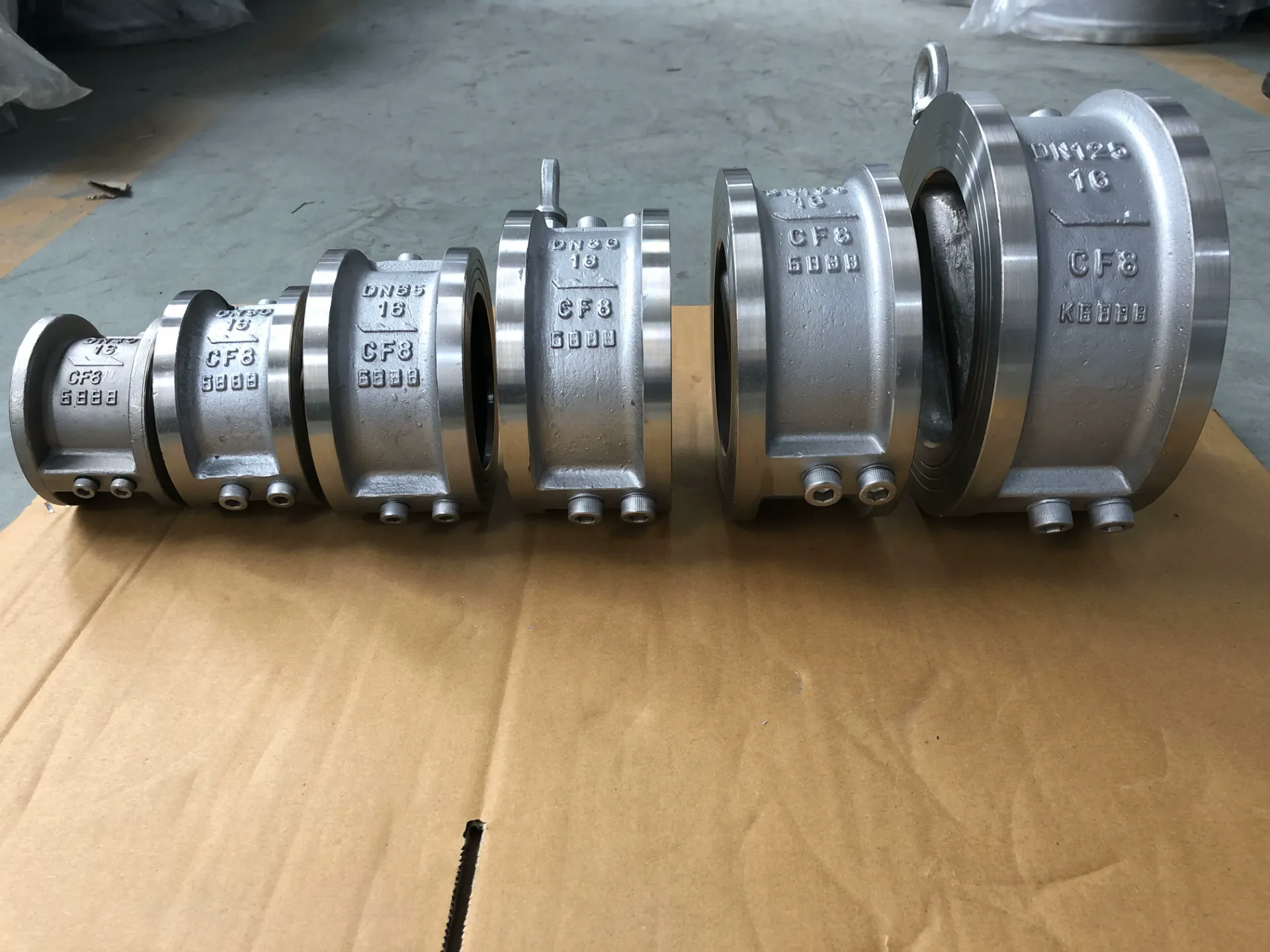
A 3-inch flange is a method of joining pipes, valves, pumps and other equipment in a piping system. It is a critical component in numerous industrial sectors, including oil and gas, chemical processing, water treatment, and power generation. Functionally, it provides a secure and reliable connection that can withstand high pressures, temperatures, and corrosive environments. Flanges are typically welded or screwed onto the ends of pipes and are then bolted together to form a joint. This guide provides an in-depth technical overview of 3-inch flanges, covering material science, manufacturing processes, performance characteristics, failure modes, and relevant industry standards. The 3-inch designation refers to the nominal pipe size, a standardized dimension used for compatibility. Core performance indicators center around pressure rating, material compatibility, and bolt circle diameter accuracy, all critical for maintaining system integrity. A key industry pain point is ensuring consistent flange facings and bolt hole alignment to prevent leaks and maintain structural integrity, alongside selecting materials resistant to the process fluid.
Material Science & Manufacturing
3-inch flanges are commonly manufactured from carbon steel (ASTM A105, API 641), stainless steel (304/304L, 316/316L - ASTM A182 F304/F304L, F316/F316L), alloy steel (ASTM A182 F11, F22), and occasionally more specialized materials like duplex stainless steel or nickel alloys depending on the application's demands. Carbon steel offers cost-effectiveness and adequate strength for many applications, but is susceptible to corrosion. Stainless steels provide superior corrosion resistance, while alloy steels are chosen for high-temperature or high-pressure services. Manufacturing begins with forging or casting the flange blank. Forging generally results in a stronger, more homogenous material structure, crucial for high-stress applications. Casting is more economical for large-scale production. Machining is then performed to create the flange face, bolt holes, and bore diameter. Critical parameters include maintaining concentricity between the bore and bolt circle, achieving precise surface finish on the flange face (to ensure gasket sealing), and dimensional accuracy of bolt holes. Welding procedures (AWS D1.1 for steel flanges) must be strictly adhered to, employing qualified welders and appropriate pre- and post-weld heat treatment to minimize residual stresses and prevent cracking. Material traceability is paramount, with mill test reports (MTRs) required to verify chemical composition and mechanical properties. Corrosion resistance is directly tied to the alloy’s chromium, nickel, and molybdenum content, influencing pitting resistance equivalent number (PREN).

Performance & Engineering
The performance of a 3-inch flange is dictated by its ability to maintain a pressure-tight seal under specified operating conditions. Force analysis involves calculating the bolt load required to compress the gasket and maintain sealing integrity. This calculation considers the internal pressure, flange diameter, gasket properties, and bolt circle diameter. Finite Element Analysis (FEA) is frequently employed to assess stress distribution within the flange and bolt assembly under various loading scenarios, identifying potential stress concentrations and optimizing flange design. Environmental resistance is crucial; corrosion is a major concern, addressed through material selection and protective coatings. Temperature cycling induces thermal stresses, which must be accounted for in the design. Compliance requirements are stringent, often dictated by ASME B16.5 (for pipe flanges and flanged fittings) and PED (Pressure Equipment Directive) for European applications. Flange facings (raised face, flat face, ring type joint) are selected based on pressure and fluid compatibility. Gasket materials (e.g., non-asbestos fiber, PTFE, metallic gaskets) must be chemically compatible with the process fluid and capable of withstanding the operating temperature and pressure. Proper bolt torque is essential; under-torque leads to leakage, while over-torque can damage the flange or gasket. A key engineering challenge is mitigating galvanic corrosion when dissimilar metals are used in the flanged joint.
Technical Specifications
| Parameter | ASTM A105 Carbon Steel | ASTM A182 F304/F304L Stainless Steel | ASTM A182 F316/F316L Stainless Steel | ASME B16.5 Pressure Rating (lbs) |
|---|---|---|---|---|
| Nominal Pipe Size | 3 inches | 3 inches | 3 inches | 150#, 300#, 600#, 900#, 1500#, 2500# |
| Material | Carbon Steel | 304/304L Stainless Steel | 316/316L Stainless Steel | - |
| Tensile Strength (MPa) | 400-550 | 517-724 | 483-790 | - |
| Yield Strength (MPa) | 250-345 | 207-276 | 241-345 | - |
| Elongation (%) | 20-25 | 30-50 | 35-55 | - |
| Corrosion Resistance | Low (requires coating) | Good | Excellent | - |
Failure Mode & Maintenance
Common failure modes for 3-inch flanges include corrosion (particularly in carbon steel), bolt failure due to fatigue or corrosion, gasket failure leading to leakage, and flange face damage from improper tightening or erosion. Fatigue cracking can occur in bolt holes due to cyclic loading. Crevice corrosion can initiate under gaskets or in areas with stagnant fluid. Delamination can occur in coated flanges if the coating is improperly applied or damaged. Oxidation at high temperatures can weaken the flange material. Failure analysis typically involves visual inspection, non-destructive testing (NDT) like ultrasonic testing (UT) and radiographic testing (RT) to detect cracks or corrosion, and material testing to verify mechanical properties. Preventive maintenance includes regular visual inspections for corrosion or damage, periodic bolt torque checks, and gasket replacement according to a predetermined schedule. Lubricating bolts prevents galling and facilitates future removal. Protective coatings (e.g., epoxy, zinc coatings) can significantly extend the service life of carbon steel flanges. Proper gasket selection and installation are critical. If corrosion is detected, the flange should be replaced or repaired by a qualified professional. Record-keeping of inspections, maintenance activities, and repairs is essential for tracking flange performance and identifying potential problems.
Industry FAQ
Q: What is the difference between a raised face (RF) and a flat face (FF) flange, and when would I choose each?
A: Raised face flanges have a raised lip around the bolt circle, providing a more concentrated sealing area. They are generally used with ring type gaskets and are preferred for higher pressure applications (typically above 150 psi). Flat face flanges have a flat sealing surface and are used with full-face gaskets, suitable for lower pressure applications or when mating to equipment with a flat surface. Selecting the appropriate face type is crucial for achieving a reliable seal.
Q: How do I determine the correct bolt torque for a 3-inch flange?
A: Bolt torque is calculated based on flange material, gasket type, flange diameter, and internal pressure. Torque values are typically provided by the flange manufacturer or can be found in ASME PCC-1 Appendix A. Using a calibrated torque wrench is essential to ensure accurate tightening. A common method is the gasket manufacturer's recommended bolt stress, which is then converted to torque.
Q: What steps should I take to prevent galvanic corrosion in a flanged joint with dissimilar metals?
A: Galvanic corrosion occurs when dissimilar metals are in electrical contact in the presence of an electrolyte. To prevent it, use compatible metals whenever possible. If dissimilar metals are unavoidable, insulate them electrically using non-conductive gaskets or sleeves. Cathodic protection can also be employed in severe environments. Careful material selection is paramount.
Q: What is the significance of the flange's pressure-temperature rating?
A: The pressure-temperature rating specifies the maximum allowable pressure the flange can withstand at a given temperature. Exceeding these limits can lead to catastrophic failure. It’s critical to verify that the flange's rating matches or exceeds the operating conditions of the piping system. These ratings are typically stamped on the flange body.
Q: What are the key considerations when selecting a gasket for a 3-inch flange?
A: Gasket selection depends on the process fluid, temperature, pressure, and flange facing. Factors to consider include chemical compatibility, temperature range, pressure rating, and sealing effectiveness. Common gasket materials include non-asbestos fiber, PTFE, and metallic gaskets. The gasket must be able to withstand the process conditions without degradation or leakage.
Conclusion
The 3-inch flange remains a foundational component in numerous industrial piping systems. Its reliable performance is contingent upon careful material selection, meticulous manufacturing processes adhering to stringent standards, and diligent maintenance protocols. Understanding the interplay between material properties, stress analysis, and environmental factors is vital for preventing failures and ensuring long-term operational integrity.
Continued advancements in non-destructive testing methodologies and coating technologies will further enhance the lifespan and reliability of 3-inch flanges. Prioritizing proper installation procedures, including accurate bolt torque and gasket selection, remains crucial. A proactive approach to inspection and maintenance, coupled with adherence to industry best practices, guarantees the secure and efficient operation of critical process infrastructure.
-
3 inch flange Performance Analysis
-
Aluminum Flange Material Performance
-
Ring Joint Flange Performance Analysis
-
Square Flange Performance Analysis
-
Ring Joint Flanges Performance Analysis
-
Rubber Flanges Performance Analysis
-
Square Flanges Material Science Manufacturing
-
Hubbed Flange Performance Analysis
-
Flat Face Flange Performance Analysis
-
Ball Valve Flange Performance Analysis
-
flat face flanges Performance Analysis
-
Flat Faced Flange Performance Analysis
-
3 in flange Performance Analysis
-
2in flange Performance Analysis
-
Flat Faced Flanges Performance Analysis
 Afrikaans
 Albanian
 Amharic
 Arabic
 Armenian
 Azerbaijani
 Basque
 Belarusian
 Bengali
 Bosnian
 Bulgarian
 Catalan
 Cebuano
 Corsican
 Croatian
 Czech
Czech
 Danish
 Dutch
Dutch
 Esperanto
 Estonian
 Finnish
 French
 Frisian
 Galician
 Georgian
 German
 Greek
Greek
 Gujarati
 Haitian Creole
 Hausa
Hawaiian
Hausa
Hawaiian
 Hebrew
 Hindi
Hindi
 Miao
Miao
 Hungarian
 Icelandic
 Igbo
Igbo
 Indonesian
 Irish
Irish
 Italian
 Japanese
 Javanese
Kannada
Javanese
Kannada
 Kazakh
 Khmer
Khmer
 Rwandese
 Korean
 Kurdish
 Kyrgyz
 Lao
Lao
 Latin
Latin
 Latvian
 Lithuanian
 Luxembourgish
 Macedonian
 Malgashi
 Malay
Malay
 Malayalam
 Maltese
 Maori
Maori
 Marathi
 Mongolian
 Myanmar
 Nepali
 Norwegian
 Norwegian
 Occitan
 Pashto
 Persian
 Polish
 Portuguese
Punjabi
Portuguese
Punjabi
 Romanian
 Russian
 Samoan
 Scottish Gaelic
 Serbian
 Sesotho
 Shona
Shona
 Sindhi
 Sinhala
 Slovak
 Slovenian
 Somali
 Spanish
 Sundanese
 Swahili
 Swedish
Tagalog
Swedish
Tagalog
 Tajik
Tajik
 Tamil
Tamil
 Tatar
Tatar
 Telugu
 Thai
Thai
 Turkish
 Turkmen
 Ukrainian
 Urdu
Urdu
 Uighur
 Uzbek
Uzbek
 Vietnamese
 Welsh
Welsh
 Bantu
Bantu
 Yiddish
 Yoruba
 Zulu
Zulu
 English