




Hubbed Flange Performance Analysis
Introduction
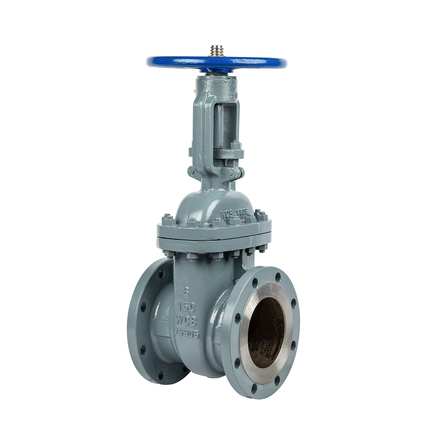
Hubbed flanges are critical components in piping systems, utilized across diverse industries including oil and gas, chemical processing, water treatment, and power generation. Functionally, they provide a secure connection between sections of pipe, valves, pumps, and other equipment. Unlike welded flanges, hubbed flanges feature a protruding hub that reinforces the connection point. This design distributes stress over a larger area, enhancing structural integrity and resisting fatigue failure, particularly under high pressure and temperature conditions. The technical position of the hubbed flange resides within the realm of pressure vessel and piping design, adhering to rigorous standards dictated by application and regulatory bodies. Core performance characteristics include pressure retention capability, leak tightness, dimensional accuracy, and resistance to corrosion and erosion. Understanding the nuances of material selection, manufacturing processes, and installation procedures is paramount for ensuring long-term operational reliability and safety.
Material Science & Manufacturing
Hubbed flanges are typically manufactured from carbon steel (ASTM A105, A36), stainless steel (304/304L, 316/316L), alloy steel (A182 F304, F316), and occasionally duplex stainless steels or more exotic alloys depending on the severity of the service conditions. Carbon steel is common for moderate temperature and pressure applications, while stainless and alloy steels offer superior corrosion resistance and higher temperature strength. Material selection hinges on chemical compatibility with the conveyed fluid, operational temperature, pressure ratings, and potential for erosion or corrosion.
The manufacturing process typically begins with forging or casting the flange blank. Forging yields a superior grain structure and mechanical properties, particularly in high-stress applications, but is generally more expensive. Casting offers greater design flexibility and cost-effectiveness for larger or more complex flange geometries. Subsequent machining operations, including facing, drilling, and threading, bring the flange to its final dimensions and specifications. Key parameter control during machining includes maintaining tight tolerances on bolt hole diameters and positions, flange face flatness (critical for sealing), and hub diameter. Heat treatment, such as annealing or quenching and tempering, may be employed to relieve residual stresses and optimize mechanical properties. Non-destructive testing (NDT) methods like ultrasonic testing (UT), magnetic particle inspection (MPI), and liquid penetrant examination (LPI) are routinely performed to detect internal flaws and surface defects, ensuring the structural integrity of the flange. Surface treatments, such as galvanizing or painting, provide additional corrosion protection.
Performance & Engineering
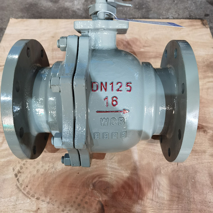
The performance of a hubbed flange is governed by several key engineering considerations. Firstly, stress analysis is crucial, particularly in high-pressure systems. The hubbed design distributes stresses more evenly than a standard flat flange, reducing the likelihood of localized yielding or fatigue cracking. Finite Element Analysis (FEA) is often employed to model stress concentrations around bolt holes and the hub area. Secondly, bolt load distribution must be carefully calculated to ensure adequate sealing pressure across the flange face. Incorrect bolt torque can lead to leakage or flange separation. Thirdly, thermal expansion and contraction are critical, especially in systems operating at elevated temperatures. Mismatch in thermal expansion coefficients between the flange and connected piping can induce significant stresses. Expansion loops and appropriate gasket selection are employed to mitigate these effects. Environmental resistance is another key factor. Corrosion, erosion, and oxidation can degrade the flange material over time, compromising its structural integrity. Material selection and protective coatings are vital for combating these degradation mechanisms. Finally, compliance with industry standards and regulations, such as ASME B16.5 (for pipe flanges and flanged fittings) and API 6A (for wellhead and Christmas tree equipment), is mandatory for ensuring safe and reliable operation.
Technical Specifications
| Parameter | ASTM A105 Carbon Steel | 304/304L Stainless Steel | A182 F316 Alloy Steel | Pressure Rating (ANSI Class 150) |
|---|---|---|---|---|
| Tensile Strength (MPa) | 400-550 | 517-724 | 483-620 | 20.68 bar (300 psi) |
| Yield Strength (MPa) | 250-345 | 205-276 | 241-345 | N/A |
| Elongation (%) | 20-30 | 30-50 | 20-35 | N/A |
| Hardness (Brinell) | 110-180 | 85-100 | 90-120 | N/A |
| Corrosion Rate (mm/year) in Seawater | 0.05-0.2 | <0.01 | <0.02 | N/A |
| Maximum Operating Temperature (°C) | 425 | 870 | 815 | N/A |
Failure Mode & Maintenance
Hubbed flanges are susceptible to several failure modes. Fatigue cracking, often initiated at bolt holes or the hub root, is a common issue in cyclic loading applications. Corrosion, particularly pitting corrosion in chloride-rich environments, can significantly reduce flange thickness and lead to leakage. Erosion, caused by abrasive particles in the fluid stream, can wear away the flange face and hub, compromising sealing performance. Bolting failures, including thread stripping and bolt fracture, are also frequent occurrences, often stemming from improper torqueing or corrosion of the bolt material. Creep, a time-dependent deformation under sustained stress, can occur at elevated temperatures. Delamination can occur in composite or layered flange constructions, if present.
Preventative maintenance is crucial for extending flange lifespan. Regular visual inspections should be conducted to identify signs of corrosion, erosion, or cracking. Bolt torque should be checked and adjusted periodically, following manufacturer’s recommendations. Protective coatings should be inspected and reapplied as needed. Gaskets should be replaced during routine maintenance schedules. NDT methods, such as UT and MPI, can be employed to detect subsurface flaws that are not visible to the naked eye. In cases of significant corrosion or cracking, flange replacement is necessary. Proper lubrication of bolt threads and flange faces during installation and maintenance is also essential to prevent galling and facilitate disassembly. Maintaining accurate records of inspections, maintenance activities, and any repairs is critical for tracking flange performance and identifying potential issues before they escalate.
Industry FAQ
Q: What is the primary advantage of a hubbed flange over a weld neck flange in high-pressure applications?
A: The hubbed flange’s extended hub provides a larger bearing surface for the bolt load, effectively distributing stress over a wider area. This reduces stress concentration around the bolt holes and at the flange root, leading to improved fatigue resistance and a higher allowable pressure rating compared to a weld neck flange of the same material and dimensions.
Q: How does material selection influence the long-term performance of a hubbed flange in a corrosive environment?
A: Material selection is paramount. Carbon steel flanges are susceptible to corrosion in many environments, requiring protective coatings. Stainless steel (304/304L, 316/316L) offers superior corrosion resistance, but even these alloys can be vulnerable to specific corrosive agents. Alloy steels, like A182 F316, provide enhanced resistance to pitting and crevice corrosion, making them suitable for harsh environments. Duplex stainless steels offer even greater corrosion resistance but at a higher cost.
Q: What are the critical considerations for bolt torque when installing a hubbed flange?
A: Proper bolt torque is vital for achieving a leak-tight seal and maintaining structural integrity. Under-torqueing can lead to leakage, while over-torqueing can stretch or yield the bolts, reducing their clamping force and potentially damaging the flange face. Torque values should be determined based on flange size, material, gasket type, and service conditions, using established torque charts and following manufacturer’s recommendations. Utilizing a calibrated torque wrench is essential for accurate torque application. A cross-torque pattern should be followed to ensure even distribution of clamping force.
Q: What non-destructive testing (NDT) methods are commonly used to inspect hubbed flanges during manufacturing and in-service?
A: Common NDT methods include Ultrasonic Testing (UT) for detecting internal flaws, Magnetic Particle Inspection (MPI) for identifying surface and near-surface cracks, Liquid Penetrant Examination (LPI) for detecting surface cracks, and Radiographic Testing (RT) for comprehensive internal inspection (although RT is less common due to safety and cost considerations). Visual Inspection (VT) is also routinely performed to identify surface defects and corrosion.
Q: What is the role of gaskets in hubbed flange connections and what types are commonly used?
A: Gaskets create a static seal between the flange faces, preventing leakage. The gasket material must be chemically compatible with the conveyed fluid and capable of withstanding the operating temperature and pressure. Commonly used gasket materials include non-asbestos fiber, spiral wound gaskets, PTFE (Teflon) gaskets, and metal gaskets. The gasket type and thickness should be selected based on the specific application requirements.
Conclusion
Hubbed flanges represent a critical component in numerous industrial applications demanding robust and reliable piping connections. Their design, specifically the reinforcing hub, offers superior stress distribution and enhanced fatigue resistance compared to alternative flange designs, making them ideally suited for high-pressure and temperature systems. Careful consideration must be given to material selection, manufacturing quality control, and proper installation procedures to ensure long-term operational integrity and prevent catastrophic failures.
Future developments in flange technology may focus on advanced materials, such as high-alloy stainless steels and composites, to further enhance corrosion resistance and reduce weight. Digitalization, including the use of sensors and data analytics for real-time monitoring of flange performance, will likely play an increasing role in preventative maintenance and predictive failure analysis. Adherence to relevant international standards and best practices remains paramount for maintaining safety and optimizing the lifecycle cost of hubbed flange systems.
-
Rubber Flanges Performance Analysis
-
Square Flanges Material Science Manufacturing
-
Hubbed Flange Performance Analysis
-
Flat Face Flange Performance Analysis
-
Ball Valve Flange Performance Analysis
-
flat face flanges Performance Analysis
-
Flat Faced Flange Performance Analysis
-
3 in flange Performance Analysis
-
2in flange Performance Analysis
-
Flat Faced Flanges Performance Analysis
-
megalug flange Performance and Engineering
-
Plate Flange Performance Analysis
-
Reducing Flange Performance Analysis
-
Sealing Flange Performance Analysis
-
Turbo Flanges Performance Analysis
 Afrikaans
 Albanian
 Amharic
 Arabic
 Armenian
 Azerbaijani
 Basque
 Belarusian
 Bengali
 Bosnian
 Bulgarian
 Catalan
 Cebuano
 Corsican
 Croatian
 Czech
Czech
 Danish
 Dutch
Dutch
 Esperanto
 Estonian
 Finnish
 French
 Frisian
 Galician
 Georgian
 German
 Greek
Greek
 Gujarati
 Haitian Creole
 Hausa
Hawaiian
Hausa
Hawaiian
 Hebrew
 Hindi
Hindi
 Miao
Miao
 Hungarian
 Icelandic
 Igbo
Igbo
 Indonesian
 Irish
Irish
 Italian
 Japanese
 Javanese
Kannada
Javanese
Kannada
 Kazakh
 Khmer
Khmer
 Rwandese
 Korean
 Kurdish
 Kyrgyz
 Lao
Lao
 Latin
Latin
 Latvian
 Lithuanian
 Luxembourgish
 Macedonian
 Malgashi
 Malay
Malay
 Malayalam
 Maltese
 Maori
Maori
 Marathi
 Mongolian
 Myanmar
 Nepali
 Norwegian
 Norwegian
 Occitan
 Pashto
 Persian
 Polish
 Portuguese
Punjabi
Portuguese
Punjabi
 Romanian
 Russian
 Samoan
 Scottish Gaelic
 Serbian
 Sesotho
 Shona
Shona
 Sindhi
 Sinhala
 Slovak
 Slovenian
 Somali
 Spanish
 Sundanese
 Swahili
 Swedish
Tagalog
Swedish
Tagalog
 Tajik
Tajik
 Tamil
Tamil
 Tatar
Tatar
 Telugu
 Thai
Thai
 Turkish
 Turkmen
 Ukrainian
 Urdu
Urdu
 Uighur
 Uzbek
Uzbek
 Vietnamese
 Welsh
Welsh
 Bantu
Bantu
 Yiddish
 Yoruba
 Zulu
Zulu
 English