


flange check valve Performance Analysis
Introduction
Flange check valves are critical components in piping systems designed to ensure unidirectional fluid flow, preventing backflow and safeguarding equipment. Positioned within the industry chain downstream of pipe fabrication and pump/compressor manufacturing, these valves represent a final line of defense against process disruptions, contamination, and potential damage. Their core performance is defined by minimal pressure drop, leak-tight shutoff, and robust durability under varying operational conditions. Unlike swing or lift check valves, flange connections provide a secure, high-integrity seal suited for high-pressure and high-temperature applications. The increasing demand for process safety and regulatory compliance drives the need for reliable and high-performance flange check valves across industries like oil & gas, chemical processing, power generation, and water treatment. A key pain point in the industry lies in selecting materials compatible with aggressive fluids and maintaining consistent valve performance over extended service lives, particularly in corrosive environments. Proper valve sizing and installation are also crucial to avoid premature failure and maintain system efficiency.
Material Science & Manufacturing
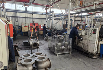
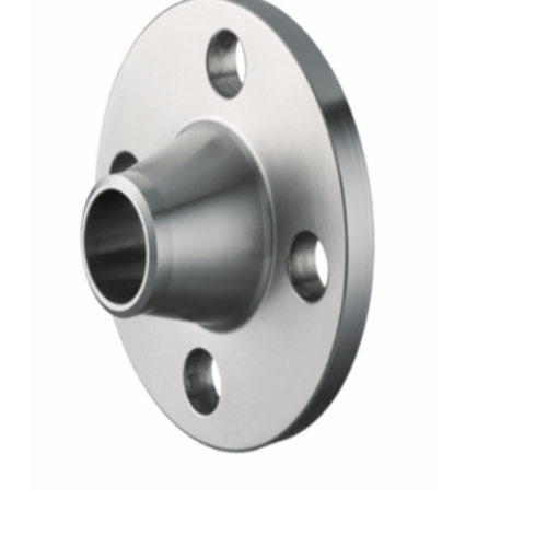
The body of a flange check valve is typically constructed from materials selected for their corrosion resistance, pressure handling capabilities, and cost-effectiveness. Common materials include carbon steel (ASTM A105), stainless steel (304/316 – ASTM A351), ductile iron (ASTM A536), and alloy steels (ASTM A182). Material selection is fundamentally linked to the fluid being conveyed; aggressive chemicals require higher alloy content or specialized polymers. The internal components, particularly the disc and seat, demand high wear resistance and sealing properties. Materials like PTFE, EPDM, or Hastelloy are frequently used for seats, while discs can be fabricated from the same body material or hardened alloys. Manufacturing processes vary depending on the body material. Carbon steel and ductile iron bodies are often produced via sand casting followed by machining to ensure dimensional accuracy and surface finish. Stainless steel and alloy steel bodies can utilize investment casting or forging for increased structural integrity. Flange faces are machined to conform to ANSI/ASME standards (e.g., Raised Face, Flat Face, Ring Type Joint) to guarantee a leak-proof connection. Welding procedures (AWS D1.1 for steel) are critical in flange attachment and require strict quality control to prevent defects like porosity and incomplete fusion. Post-weld heat treatment (PWHT) may be necessary to relieve residual stresses. Quality control throughout manufacturing involves non-destructive testing (NDT) like radiography, ultrasonic testing, and liquid penetrant inspection to verify weld integrity and material soundness. Parameter control during machining (cutting speed, feed rate, coolant application) is essential to achieve the required surface roughness and dimensional tolerances.
Performance & Engineering
The performance of a flange check valve hinges on its ability to withstand fluid pressure, maintain a leak-tight seal, and minimize pressure loss. Force analysis involves evaluating the hydrodynamic forces acting on the disc, particularly during opening and closing cycles. These forces are influenced by flow velocity, fluid density, and disc geometry. The spring mechanism (in spring-loaded check valves) must be designed to overcome these forces and ensure rapid closure. Environmental resistance is a major concern, especially in outdoor applications or corrosive environments. Material selection must account for factors like galvanic corrosion, erosion, and UV degradation. Compliance with industry standards such as API 598 (Valve Inspection and Testing) and ASME Section XI (Rules for Inservice Inspection of Nuclear Power Plant Components) is essential for ensuring safety and reliability. Functional implementation relies on accurate valve sizing based on flow rate, fluid properties, and system pressure. Undersized valves can lead to excessive pressure drop and cavitation, while oversized valves may not close effectively, allowing backflow. Fatigue analysis is crucial for valves subjected to frequent cycling, predicting the lifespan of critical components like the disc and spring. The Cv (flow coefficient) value is a key engineering parameter used to quantify the valve's flow capacity. Pressure drop calculations are performed using Bernoulli's equation and incorporating the valve's resistance coefficient (K-factor). The impact of fluid viscosity and temperature on valve performance must also be considered.
Technical Specifications
| Parameter | Unit | Typical Value (Carbon Steel) | Typical Value (Stainless Steel 316) |
|---|---|---|---|
| Maximum Operating Pressure | psi | 2500 | 2000 |
| Maximum Operating Temperature | °F | 450 | 600 |
| Connection Type | - | ANSI/ASME B16.5 RF/FF/RTJ | ANSI/ASME B16.5 RF/FF/RTJ |
| Body Material | - | ASTM A105 | ASTM A351 CF8M |
| Disc Material | - | ASTM A105 | ASTM A351 CF8M |
| Seat Material | - | PTFE | PTFE |
| Cv (Flow Coefficient) – 2” Valve | Gallons per Minute (GPM) | 350 | 330 |
Failure Mode & Maintenance
Flange check valves are susceptible to several failure modes. Fatigue cracking can occur in the disc or body due to repeated stress cycles, particularly at stress concentration points. Corrosion, both general and localized (pitting, crevice corrosion), can weaken the valve body and disc, leading to leakage. Erosion, caused by abrasive particles in the fluid stream, can damage the seat and disc surfaces, reducing sealing efficiency. Disc sticking, often due to debris accumulation or corrosion products, prevents proper closure, resulting in backflow. Delamination of the seat material can occur due to thermal cycling or chemical attack. Oxidation, especially at high temperatures, can degrade the valve’s metallic components. Maintenance strategies involve regular visual inspections for signs of corrosion or leakage. Periodic testing of the valve’s sealing capability is crucial. Lubrication of moving parts (if applicable) prevents sticking. Preventative maintenance schedules should include cleaning to remove debris and corrosion inhibitors to protect against corrosion. In case of leakage, the seat should be inspected and replaced if necessary. Welded connections should be periodically inspected for cracks or corrosion. Non-destructive testing (NDT) methods can be used to assess the integrity of critical components. Proper storage and handling are essential to prevent damage during transportation and installation. A comprehensive maintenance log should be maintained to track inspection results, repairs, and replacements.
Industry FAQ
Q: What is the impact of fluid hammer on a flange check valve, and how can it be mitigated?
A: Fluid hammer, caused by sudden changes in flow velocity, can generate significant pressure surges that exceed the valve's pressure rating, leading to disc damage or body failure. Mitigation strategies include using slow-closing check valves, incorporating surge suppressors (air chambers or accumulators) in the piping system, and optimizing pump start/stop procedures to minimize flow velocity changes. Properly sized valves, aligned correctly, also minimize risk.
Q: How does the choice of seat material affect the valve’s leak rate and longevity?
A: Seat material directly impacts leak rate and longevity. Elastomeric seats (e.g., EPDM, Buna-N) offer good sealing but limited temperature and chemical resistance. PTFE seats provide broader chemical compatibility but may exhibit creep and require periodic replacement. Metal seats provide high-temperature capability and durability but generally have higher leak rates. Selecting the appropriate material based on fluid properties and operating conditions is critical.
Q: What are the implications of using a flange check valve in a slurry application?
A: Slurry applications introduce abrasive particles that can cause severe erosion of the disc and seat, leading to premature failure. Valves designed for slurry service typically incorporate hardened materials, streamlined flow paths, and larger clearances to minimize wear. Regular inspection and replacement of wear parts are essential. Consider valves specifically designated as ‘slurry’ valves.
Q: How do flange check valves conform to pressure vessel directives like the PED (Pressure Equipment Directive)?
A: Flange check valves falling under the scope of the PED (2014/68/EU) require CE marking and must be manufactured in accordance with the directive's requirements. This involves material traceability, weld procedure qualification, non-destructive testing, and documentation. A notified body assesses the manufacturer’s quality system and verifies compliance.
Q: What are the considerations for installing a flange check valve in a vertical pipeline?
A: In vertical pipelines, the weight of the disc can affect its closing speed and sealing performance. A spring-assisted check valve is often preferred to ensure positive closure. The orientation of the valve should be carefully considered to minimize the accumulation of debris on the seat. Proper support and alignment of the pipeline are also crucial to prevent stress on the valve flange connections.
Conclusion
Flange check valves, while seemingly simple components, represent a critical safeguard in fluid handling systems. Their selection and implementation demand a detailed understanding of material science, manufacturing processes, performance characteristics, and potential failure modes. Proper material selection aligned with the conveyed fluid’s characteristics and operational temperature is paramount for longevity and preventing catastrophic failure. Thorough adherence to relevant industry standards, coupled with a robust maintenance program, ensures consistent and reliable performance, minimizing downtime and maximizing system efficiency.
Looking forward, advancements in valve design will focus on minimizing pressure drop, enhancing sealing performance, and developing smart valve technologies with integrated sensors for real-time monitoring and predictive maintenance. The use of advanced materials, such as ceramic composites and high-alloy steels, will further extend the service life of these valves in harsh environments. Digital integration and remote monitoring capabilities will play an increasingly important role in optimizing valve performance and reducing operational costs.
-
Top Reasons to Choose a Stainless Steel Flange Check Valve for Industrial Applications
-
12 inch check valve Performance Analysis
-
lift check valves Performance Engineering
-
check valve 12 inch Performance Analysis
-
stop check valve Performance Analysis
-
check stop valve Performance Analysis
-
stop check valves Performance Analysis
-
pilot operated check valve Performance Analysis
-
spring loaded check valve Material Science Manufacturing
-
pilot operated check valves Performance Analysis
-
check valve pilot operated Performance Analysis
-
1 4 in check valve Performance Engineering
-
check valve 3 4 Performance Analysis
-
11 2 check valve Performance Analysis
-
spring check valve Material Science Manufacturing