


flange ball valve Performance Analysis
Introduction
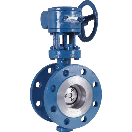
Flange ball valves are quarter-turn rotary motion valves used to control the flow of a fluid, gas, or slurry. Characterized by a hollow, perforated and pivoting ball, they are integral to numerous industrial processes across sectors including oil and gas, chemical processing, water treatment, and power generation. Their positioning within the industrial chain is critical; they function as control and isolation points within complex piping systems, often dictating process efficiency and safety. Core performance attributes of flange ball valves center around tight shut-off capabilities, minimal pressure drop when fully open, and robust durability to withstand harsh operating conditions. Industry pain points commonly revolve around selecting appropriate materials for corrosive media, ensuring leak-tightness over extended periods, and maintaining consistent torque operation as pressure and temperature fluctuate. The prevalence of stringent safety regulations and the increasing demand for process optimization drives the need for high-performance, reliable flange ball valve solutions.
Material Science & Manufacturing
The body of a flange ball valve is commonly constructed from carbon steel (ASTM A105), stainless steel (304/316, per ASTM A351), or alloy steels (e.g., Inconel, Hastelloy) depending on the fluid compatibility requirements. Carbon steel offers cost-effectiveness for non-corrosive applications, while stainless steel provides enhanced corrosion resistance. Alloy steels are chosen for extremely corrosive or high-temperature environments. The ball itself is typically manufactured from hardened stainless steel (410, 316) to ensure wear resistance and maintain sealing integrity. Seals are critical and are often composed of PTFE (Teflon), reinforced PTFE, or other elastomers like Viton, selected based on temperature and chemical compatibility. Manufacturing typically involves precision casting or forging for the body, followed by machining to exacting tolerances. The ball is manufactured through cold forging or machining, undergoing heat treatment to achieve the desired hardness. Key parameter control during manufacturing includes dimensional accuracy of the ball and seat, surface finish to minimize friction, and weld quality for flange connections (meeting AWS D1.1 standards). The seating material is lapped and polished to achieve a leak-tight seal, typically exceeding 99.99% closure. Non-destructive testing (NDT) methods like radiography, ultrasonic testing, and liquid penetrant inspection are employed to verify weld integrity and identify material defects. The flange dimensions adhere to ANSI/ASME B16.5 standards to ensure interchangeability and proper bolting.
Performance & Engineering
Flange ball valve performance is heavily reliant on force analysis of the ball against the seat. This force is generated by the spring-loaded seats or by the differential pressure across the valve. Engineers must consider the stem loading and bearing area to prevent stem extrusion under high pressure. Environmental resistance is paramount, particularly concerning temperature cycling and exposure to corrosive fluids. Thermal expansion and contraction of valve components can induce stresses, potentially leading to leakage. Material selection must account for these factors. Compliance requirements often include API 6D (Ball Valves), ASME B31.3 (Process Piping), and PED (Pressure Equipment Directive) for European applications. Functional implementation necessitates careful consideration of actuation methods - manual, pneumatic, hydraulic, or electric. Pneumatic actuators require calculations for air supply pressure and cylinder sizing to achieve the required torque for full valve operation. Hydraulic actuators necessitate consideration of fluid compatibility and pressure limitations. Electric actuators need precise motor sizing and control logic to ensure accurate positioning. Cavitation is a critical concern in liquid applications. The valve's internal geometry and flow rate must be optimized to avoid cavitation, which can cause significant erosion and damage to the ball and seat. Torque calculations must account for the fluid's viscosity and density, as well as the valve’s internal friction.
Technical Specifications
| Parameter | Unit | Standard Specification (Carbon Steel) | Standard Specification (316 Stainless Steel) |
|---|---|---|---|
| Maximum Operating Pressure | psi | 2500 | 2000 |
| Temperature Range | °F | -20 to 450 | -40 to 500 |
| Body Material | - | ASTM A105 | ASTM A351 CF8M |
| Ball Material | - | 410 Stainless Steel | 316 Stainless Steel |
| Seat Material | - | PTFE | PTFE |
| End Connection | - | ANSI B16.5 RF, FF | ANSI B16.5 RF, FF |
| Actuation Type | - | Manual, Pneumatic, Electric | Manual, Pneumatic, Electric |
Failure Mode & Maintenance
Common failure modes in flange ball valves include seat erosion (due to abrasive particles in the fluid), ball scratching or pitting (from solids impact), stem leakage (from seal degradation or stem damage), and body cracking (from overpressure or fatigue). Fatigue cracking typically occurs at stress concentration points around the flanges or stem bore. Delamination of the seat material can occur due to improper installation or exposure to incompatible chemicals. Degradation of the seat material (PTFE) can happen at elevated temperatures or due to chemical attack. Oxidation of metallic components can occur in high-temperature, oxidizing environments. Failure analysis should begin with a thorough visual inspection, followed by NDT methods to identify cracks or defects. Maintenance solutions include regular inspection of seals and replacement as needed, lubrication of the stem and bearings, torque checking of flange bolts, and periodic testing to verify leak-tightness. For severe failures, complete valve replacement may be necessary. Preventative maintenance schedules should be implemented based on operating conditions and fluid characteristics. A critical step in maintaining performance is adhering to manufacturer's recommended operating parameters and avoiding over-torquing during installation, which can damage the seat. Regular cleaning to remove debris buildup is also essential.
Industry FAQ
Q: What is the primary difference between a floating ball valve and a trunnion mounted ball valve, and when would you recommend each type?
A: Floating ball valves utilize a ball that is held in place by the seats, allowing it to "float" between them. They are suitable for lower pressure and temperature applications. Trunnion mounted ball valves, conversely, have a ball supported by trunnions at the top and bottom, allowing for higher pressure and temperature capabilities and reduced operating torque. We recommend trunnion mounted valves for high-pressure, high-temperature, and larger diameter applications, while floating ball valves are suitable for less demanding services.
Q: How does the selection of seat material impact the valve’s performance in corrosive environments?
A: Seat material compatibility is critical in corrosive environments. PTFE offers broad chemical resistance but has temperature limitations. Reinforced PTFE provides enhanced mechanical strength and temperature resistance. Other elastomers like Viton, EPDM, and Kalrez offer specific chemical resistance profiles. Selecting the incorrect seat material can lead to rapid degradation, leakage, and ultimately, valve failure. Detailed chemical compatibility charts should be consulted prior to selection.
Q: What are the key considerations when specifying a flange ball valve for cryogenic applications?
A: Cryogenic applications require materials that maintain ductility at extremely low temperatures. Stainless steel (304L, 316L) is commonly used, and special low-temperature PTFE seals are essential to prevent hardening and leakage. Thermal contraction must be carefully considered during installation to avoid stress on the valve body and connections. Valves should also be tested to ensure leak-tightness at cryogenic temperatures.
Q: What is the significance of a valve’s Cv value, and how does it relate to flow capacity?
A: The Cv value (coefficient of flow) is a measure of a valve’s ability to pass fluid. A higher Cv value indicates a greater flow capacity. It’s essential for calculating pressure drop across the valve and ensuring the valve can meet the required flow rate for the application. Accurate Cv values are provided by manufacturers and should be used in flow calculations.
Q: What maintenance procedures are critical for extending the service life of a pneumatically actuated flange ball valve?
A: Regular inspection of the pneumatic actuator, including air filter maintenance, cylinder seal checks, and solenoid valve testing, is critical. Proper lubrication of actuator components is also essential. Monitoring air supply pressure and ensuring it remains within the specified range prevents actuator malfunction. Periodic testing of the valve's actuation speed and torque output ensures optimal performance.
Conclusion
Flange ball valves represent a vital component in numerous industrial fluid control systems. Their robust design, coupled with the versatility offered by material selection and actuation methods, makes them suitable for a wide array of applications. Understanding the underlying material science, manufacturing processes, and potential failure modes is paramount for ensuring reliable operation and minimizing downtime. Selection criteria must prioritize fluid compatibility, pressure and temperature ratings, and compliance with relevant industry standards.
The future of flange ball valve technology is geared towards improved sealing materials, enhanced automation capabilities, and integration with predictive maintenance systems. Advancements in materials science will lead to the development of more durable and corrosion-resistant valve components, while smart valve technologies will enable real-time monitoring of valve performance and early detection of potential failures. Continued adherence to stringent quality control and meticulous maintenance practices will remain essential for maximizing the lifespan and reliability of these critical industrial assets.
-
Top Reasons to Choose a Stainless Steel Flange Check Valve for Industrial Applications
-
12 inch check valve Performance Analysis
-
lift check valves Performance Engineering
-
check valve 12 inch Performance Analysis
-
stop check valve Performance Analysis
-
check stop valve Performance Analysis
-
stop check valves Performance Analysis
-
pilot operated check valve Performance Analysis
-
spring loaded check valve Material Science Manufacturing
-
pilot operated check valves Performance Analysis
-
check valve pilot operated Performance Analysis
-
1 4 in check valve Performance Engineering
-
check valve 3 4 Performance Analysis
-
11 2 check valve Performance Analysis
-
spring check valve Material Science Manufacturing