


electric check valves Performance Analysis
Introduction
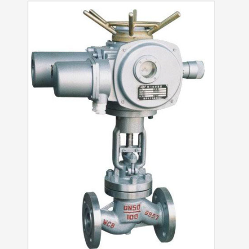
Electric check valves are self-acting valves that permit fluid flow in only one direction and are remotely controlled via an electric actuator. They represent a critical component in diverse industrial applications including water treatment, chemical processing, oil and gas pipelines, and power generation systems, where unidirectional flow control and remote operation are paramount. Unlike conventional check valves relying solely on pressure differential, electric check valves offer the added capability of controlled opening and closing, enabling precise flow regulation and preventing backflow even under low or fluctuating pressure conditions. Their technical position in the industry chain lies downstream from valve body manufacturing, actuator production, and control system integration. Core performance characteristics are defined by flow coefficient (Cv), leakage rate (measured in terms of seat leakage class – Class V, IV, III, etc.), actuation speed, operating pressure range, and material compatibility with the conveyed fluid. The primary industry pain point addressed by electric check valves is the need for reliable, remotely operated backflow prevention in complex process systems, particularly where manual intervention is impractical or hazardous.
Material Science & Manufacturing
The construction of electric check valves typically involves several key materials. Valve bodies are frequently fabricated from ductile iron (ASTM A536-83), stainless steel (304/316 – ASTM A240), or alloy steels, selected for their corrosion resistance, pressure-bearing capacity, and compatibility with the process fluid. The disc, responsible for blocking reverse flow, is commonly made from stainless steel, PTFE (Polytetrafluoroethylene), or elastomers like EPDM (Ethylene Propylene Diene Monomer) depending on temperature, pressure, and chemical requirements. The electric actuator housing generally uses aluminum alloy (ADC12) for lightweight construction and effective heat dissipation. Manufacturing processes vary based on the valve size and material. Ductile iron bodies are created using sand casting, followed by surface treatment (epoxy coating – SSPC SP10) for corrosion protection. Stainless steel bodies utilize investment casting or forging. The disc is often machined to precise tolerances to ensure tight sealing. Actuator assembly involves winding coils, mounting gear trains, and integrating electronic control components. Critical parameter control during manufacturing includes dimensional accuracy of the disc and seat (to maintain seat leakage class specifications), surface roughness of sealing surfaces (Ra < 0.8 µm), and actuator torque calibration. Welding, where applicable (e.g., connecting actuator to body) must adhere to ASME Section IX standards to ensure structural integrity. Heat treatment is employed for alloy steel components to achieve desired hardness and toughness, governed by ASTM A275/A276 guidelines.
Performance & Engineering
Performance evaluation of electric check valves centers on flow characteristics, actuation speed, and long-term reliability. Force analysis involves calculating the hydrodynamic forces acting on the disc during flow and the torque required from the actuator to overcome these forces and fully open/close the valve. Environmental resistance is critical, especially in harsh industrial environments. Valves operating in corrosive atmospheres require robust materials and protective coatings. IP65/IP67 ingress protection ratings (IEC 60529) are standard to prevent damage from dust and water. Compliance requirements vary by region and application. For potable water systems, valves must comply with NSF/ANSI 61 standards. For hazardous locations, ATEX or IECEx certification is essential. Functional implementation involves integrating the valve with a Programmable Logic Controller (PLC) or Distributed Control System (DCS) via a 4-20mA signal or digital communication protocols (Modbus, Profibus). Valve selection also demands consideration of fluid velocity; excessive velocity can lead to cavitation and erosion, reducing valve lifespan. Proper sizing, based on flow rate and pressure drop calculations, is therefore crucial to prevent performance degradation and ensure optimal valve operation. Fatigue analysis, utilizing finite element modeling (FEM), is employed during the design phase to assess the valve's resistance to cyclic loading and prevent premature failure.
Technical Specifications
| Parameter | Unit | Typical Range | Test Standard |
|---|---|---|---|
| Maximum Operating Pressure | psi | 150-600 | API 598 |
| Valve Size (DN) | mm | 50-600 | ANSI B16.10 |
| Actuator Supply Voltage | V | 24V DC, 110/220V AC | IEC 60038 |
| Actuation Time (Open/Close) | seconds | 2-30 | Manufacturer's Specification |
| Leakage Rate (Seat Leakage Class) | ppm | Class V (Bubble-Tight) | FCI 70-2 |
| Body Material | - | Ductile Iron, SS316 | ASTM A240, ASTM A536 |
Failure Mode & Maintenance
Electric check valves, while robust, are susceptible to several failure modes. Fatigue cracking of the valve body, particularly near welds, can occur due to cyclic pressure loading and thermal stress. Corrosion, especially in aggressive fluid environments, can lead to pitting and erosion of internal components. Disc binding, caused by debris accumulation or improper alignment, prevents proper sealing. Actuator failure can manifest as sluggish operation, inability to fully open/close, or complete electrical malfunction. Seal degradation, resulting from chemical attack, temperature extremes, or mechanical wear, leads to increased leakage. Failure analysis typically involves visual inspection, non-destructive testing (NDT – ultrasonic testing, radiographic testing), and material analysis (metallography). Preventative maintenance is crucial. Regular inspection of the actuator, lubrication of moving parts, and cleaning of valve internals are recommended. Periodic testing of the valve's sealing performance using pressure testing is essential. Replacement of worn seals and actuator components should be performed according to the manufacturer's schedule. For corrosion mitigation, appropriate material selection and application of protective coatings are vital. In cases of actuator failure, a complete actuator replacement or repair by a qualified technician is necessary. Regular torque checks on the actuator ensure optimal performance and prevent overstressing the valve mechanism.
Industry FAQ
Q: What is the primary advantage of an electric check valve over a traditional swing check valve in a low-flow application?
A: Traditional swing check valves rely on backflow to initiate closure. In low-flow scenarios or with fluids of low density, this backflow force may be insufficient for consistent sealing, leading to leakage. Electric check valves, controlled by an actuator, positively shut off the flow regardless of fluid velocity or density, ensuring superior backflow prevention.
Q: How do I determine the correct actuator size for a specific electric check valve application?
A: Actuator sizing depends on several factors: valve size, fluid type, operating pressure, and desired actuation speed. The actuator must generate sufficient torque to overcome the hydrodynamic forces acting on the disc and any friction within the valve. Manufacturers provide sizing calculations or recommend actuators based on application data. Proper sizing prevents actuator overload and ensures reliable operation.
Q: What are the common causes of seat leakage in electric check valves and how can they be addressed?
A: Common causes include debris lodged between the seat and disc, wear or damage to the sealing surfaces, and improper actuator positioning. Addressing this involves cleaning the valve internals, replacing worn seals, and recalibrating the actuator to ensure complete closure. Regular inspection and preventative maintenance are key.
Q: What level of ingress protection (IP rating) is recommended for an electric check valve operating outdoors in a harsh environment?
A: For outdoor applications exposed to rain, dust, and extreme temperatures, an IP65 or IP67 rating is highly recommended. IP65 provides protection against dust ingress and low-pressure water jets, while IP67 offers complete protection against dust and the effects of temporary immersion in water.
Q: What documentation should I expect from a reputable electric check valve manufacturer?
A: Reputable manufacturers should provide comprehensive documentation including: a detailed product specification sheet, installation and operating manuals, maintenance schedules, material test reports (MTRs) confirming material traceability and compliance, and dimensional drawings. They should also be able to provide compliance certificates for relevant industry standards (NSF, ATEX, IECEx).
Conclusion
Electric check valves represent a significant advancement in backflow prevention technology, offering enhanced control, reliability, and remote operability compared to traditional mechanical check valves. Their ability to function effectively in low-flow conditions and hazardous environments, coupled with integration capabilities within modern control systems, makes them indispensable in a wide range of industrial applications.
Selecting the appropriate electric check valve necessitates a thorough understanding of the process fluid, operating conditions, and relevant industry standards. Prioritizing high-quality materials, precise manufacturing processes, and proactive maintenance strategies will ensure long-term performance, minimize downtime, and maximize return on investment.
-
Top Reasons to Choose a Stainless Steel Flange Check Valve for Industrial Applications
-
electric check valve Performance Engineering
-
electric check valves Performance Analysis
-
Threaded Check Valves Performance Analysis
-
6 inch check valve Performance Analysis
-
8 check valve Performance Analysis
-
diaphragm check valve Material Science Manufacturing
-
dual plate check valve Performance Analysis
-
check valve 6 inch Material Science
-
diaphragm check valves Performance Analysis
-
dual plate check valves Performance Analysis
-
vertical check valves Material Science Manufacturing
-
8 check valves Performance Analysis
-
refrigeration check valves Performance Analysis
-
pilot check valve Performance Analysis