


12 inch check valve Performance Analysis
Introduction
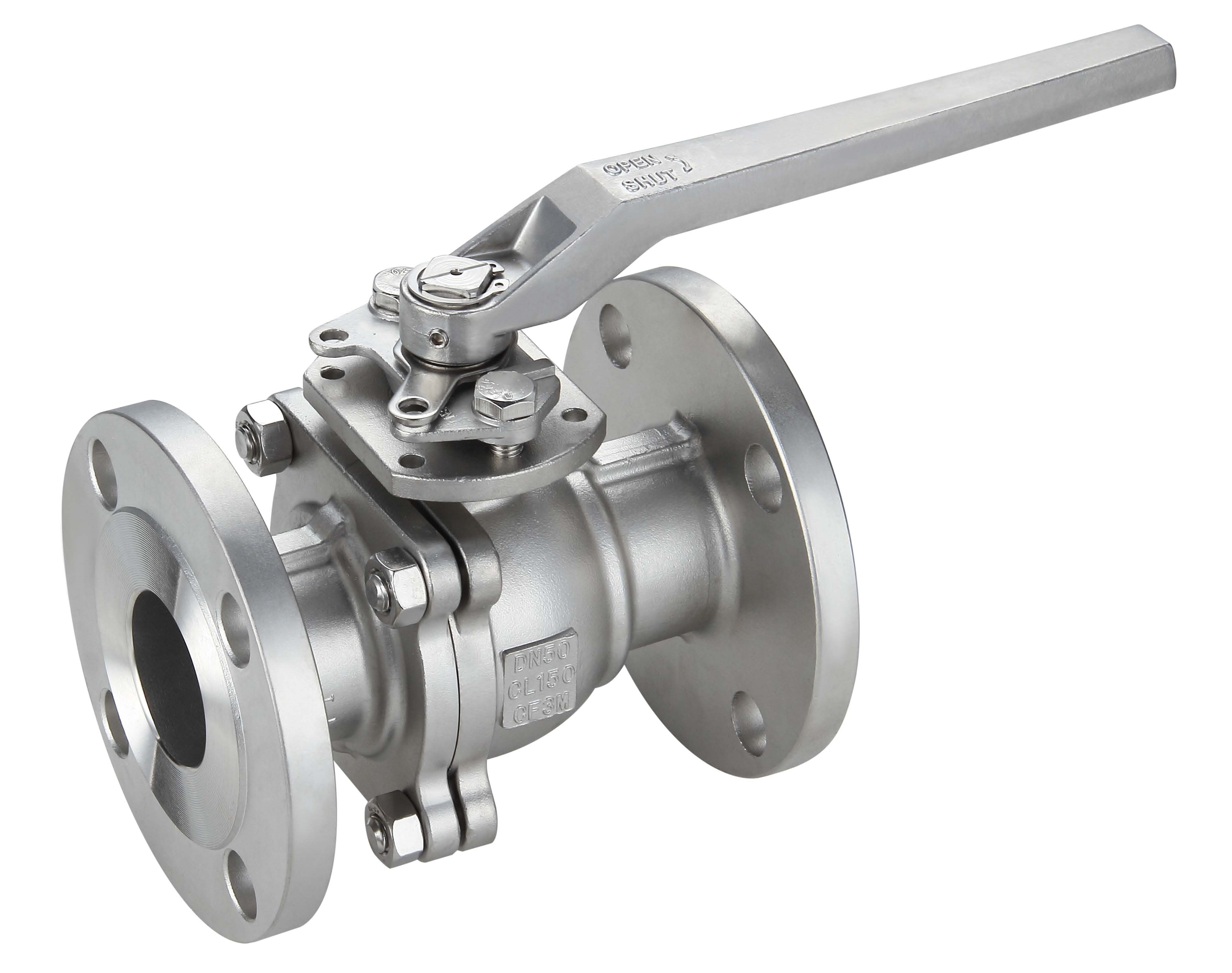
A 12-inch check valve is a mechanical device utilized within piping systems to ensure unidirectional fluid flow. It operates automatically, permitting flow in only one direction and preventing backflow. Positioned within the broader industrial fluid handling chain – encompassing pumps, pipelines, storage tanks, and process equipment – the 12-inch check valve is crucial for system integrity, operational efficiency, and safety. Its key performance characteristics include its pressure rating, flow coefficient (Cv), leakage rate (expressed as bubbles/minute or percentage of flow), and materials of construction. A primary industry pain point is selecting a valve material compatible with the conveyed fluid to avoid corrosion and premature failure, particularly in aggressive chemical processing or wastewater treatment applications. Another critical concern is maintaining a low pressure drop across the valve to minimize energy consumption, especially in high-volume flow scenarios.
Material Science & Manufacturing
The body of a 12-inch check valve is commonly manufactured from cast iron (ASTM A126 Class B), ductile iron (ASTM A536 65-45-12), stainless steel (304/316 - ASTM A351), or alloy steels (e.g., CF8M – ASTM A351). Cast iron provides cost-effectiveness and reasonable strength for low-pressure applications, but is susceptible to corrosion. Ductile iron offers improved ductility and impact resistance. Stainless steel provides superior corrosion resistance, essential for handling corrosive fluids. Alloy steels are used for high-temperature and high-pressure services. The disc, the primary flow-controlling element, utilizes materials similar to the body, often incorporating elastomers like EPDM, Viton, or PTFE for sealing. Manufacturing processes vary depending on the material. Cast iron and ductile iron valves are produced via sand casting, followed by machining and surface treatment (epoxy coating or galvanizing). Stainless steel valves are often investment cast or forged. Welding procedures (SMAW, GTAW, FCAW – conforming to ASME Section IX) are critical for joining valve components, requiring strict control of heat input, shielding gas composition, and welder qualification to ensure weld integrity. Parameter control during casting involves precise temperature maintenance of the molten metal, sand composition, and cooling rates to minimize porosity and defects. Elastomeric seals are typically molded and then bonded to the disc using vulcanization processes, requiring precise temperature and pressure control for optimal adhesion.
Performance & Engineering
The performance of a 12-inch check valve is fundamentally governed by fluid dynamics and mechanical stress analysis. Force analysis focuses on the impact forces exerted by the fluid on the disc during opening and closing cycles. These forces must be adequately withstood by the disc and hinge mechanism to prevent deformation and fatigue failure. Environmental resistance is crucial, with considerations for temperature variations, external pressure, and potential exposure to UV radiation. Valves must meet pressure-temperature ratings specified by ANSI/ASME B16.34. Compliance requirements also include adherence to standards for materials traceability (ASTM standards), non-destructive testing (NDT – ASME Section V), and hydrostatic testing (API 598). The functional implementation of a check valve relies on its internal design, commonly utilizing swing, lift, or ball check mechanisms. Swing check valves offer minimal pressure drop but are susceptible to water hammer. Lift check valves provide positive sealing but exhibit higher pressure drop. Ball check valves are ideal for handling slurries and viscous fluids. A key engineering consideration is preventing cavitation, particularly in liquid applications, by ensuring sufficient backpressure and avoiding excessive flow velocities. The valve’s spring mechanism (where applicable) requires careful selection of material and spring rate to ensure reliable operation over extended periods and temperature ranges.
Technical Specifications
| Parameter | Unit | Typical Value (Carbon Steel) | Typical Value (Stainless Steel 316) |
|---|---|---|---|
| Nominal Pipe Size | inches | 12 | 12 |
| Maximum Operating Pressure | psi | 200 | 150 |
| Temperature Range | °F | -20 to 450 | -20 to 600 |
| Connection Type | - | Flanged (ANSI B16.5) | Flanged (ANSI B16.5) |
| Flow Coefficient (Cv) | gallons per minute per psi | 600 | 550 |
| Leakage Rate | bubbles/minute (air) | <5 | <2 |
| Weight (approximate) | lbs | 150 | 175 |
Failure Mode & Maintenance
Common failure modes for 12-inch check valves include disc erosion due to abrasive particles in the fluid, seat damage leading to leakage, spring fatigue in spring-loaded designs, and corrosion of valve body and disc. Fatigue cracking can occur in the disc or hinge mechanism under cyclic loading. Delamination of elastomeric seals is another frequent issue, particularly with prolonged exposure to high temperatures or aggressive chemicals. Oxidation and corrosion are prevalent in carbon steel valves operating in corrosive environments. Failure analysis often involves visual inspection, dye penetrant testing (ASTM E165), radiographic testing (ASTM E94), and metallurgical analysis to identify the root cause. Maintenance procedures include regular inspection of the disc and seat for wear and damage, lubrication of moving parts, and replacement of worn seals. For flanged connections, bolt tightening should be periodically checked and adjusted. Preventive maintenance programs should incorporate regular backwashing to remove debris, particularly in slurry applications. For valves exposed to corrosive fluids, periodic coating inspection and repair are crucial. Complete valve replacement may be necessary if significant corrosion or erosion is detected, or if the valve consistently fails to meet leakage rate specifications. Proper storage practices are also vital to prevent corrosion during periods of inactivity.
Industry FAQ
Q: What material selection criteria are most important when handling seawater?
A: When handling seawater, corrosion resistance is paramount. Stainless steel alloys, specifically 316 or duplex stainless steel, are highly recommended due to their superior chloride pitting resistance. Consideration should also be given to biofouling; coatings such as epoxy or specialized marine coatings may be necessary. The elastomeric seal material must be compatible with saltwater and resistant to degradation.
Q: How does the valve's internal design (swing vs. lift) affect pressure drop and water hammer potential?
A: Swing check valves generally have a lower pressure drop due to their streamlined flow path, but they are more prone to water hammer, especially during rapid closure. Lift check valves offer a positive shut-off and reduce water hammer risk, but they exhibit a higher pressure drop because the fluid is forced to change direction abruptly. The application requirements dictate the optimal design.
Q: What are the implications of exceeding the maximum operating pressure rating?
A: Exceeding the maximum operating pressure rating can lead to catastrophic valve failure, including body rupture, disc damage, or seal failure. This poses a significant safety hazard and can result in costly downtime and system damage. Pressure relief devices should be installed upstream of the valve to prevent overpressurization.
Q: What NDT methods are typically used to verify weld quality during valve manufacturing?
A: Common NDT methods include visual inspection (VT), dye penetrant testing (PT), magnetic particle testing (MT), and radiographic testing (RT). RT is often used for critical welds to detect internal defects. Ultrasonic testing (UT) can also be employed. The specific NDT methods employed are dictated by the applicable codes and standards (e.g., ASME Section V).
Q: How often should the valve be inspected for internal wear and seal degradation?
A: The inspection frequency depends on the severity of the operating conditions and the fluid being handled. As a general guideline, inspection should be conducted annually for clean fluids and more frequently (e.g., quarterly) for abrasive or corrosive fluids. Regular monitoring of pressure drop and leakage rate can provide early indications of internal wear or seal degradation.
Conclusion
The 12-inch check valve serves as a critical component in numerous industrial fluid systems, demanding careful consideration of material selection, manufacturing processes, and operational parameters. Proper selection hinges on a thorough understanding of the fluid’s properties, the system’s pressure and temperature requirements, and applicable industry standards. Failure to adequately address these factors can result in premature valve failure, system inefficiencies, and potential safety hazards.
Looking forward, advancements in valve technology will likely focus on developing more durable materials, improving sealing mechanisms to minimize leakage, and incorporating smart sensor technology for real-time performance monitoring and predictive maintenance. Further refinement of computational fluid dynamics (CFD) modeling will enable more accurate prediction of valve performance and optimization of internal designs. Implementing comprehensive maintenance programs and adhering to established industry best practices remains essential for ensuring the long-term reliability and efficiency of these critical components.
-
Top Reasons to Choose a Stainless Steel Flange Check Valve for Industrial Applications
-
12 inch check valve Performance Analysis
-
lift check valves Performance Engineering
-
check valve 12 inch Performance Analysis
-
stop check valve Performance Analysis
-
check stop valve Performance Analysis
-
stop check valves Performance Analysis
-
pilot operated check valve Performance Analysis
-
spring loaded check valve Material Science Manufacturing
-
pilot operated check valves Performance Analysis
-
check valve pilot operated Performance Analysis
-
1 4 in check valve Performance Engineering
-
check valve 3 4 Performance Analysis
-
11 2 check valve Performance Analysis
-
spring check valve Material Science Manufacturing